



- Room 1807, Unit 9, Building 2, Shangxing Commercial Street, Shangde Road, Shangxing Community, Xinqiao Subdistrict, Bao'an District, Shenzhen City, China
CONTACT US

WhatsApp


Contact Us
Our team is on stand by, waiting toassist you.

Videos
A large collection of educational videos and tutorials.

About Us
Learn about our company, leadership, and mission totransform manufacturing.

Privacy Policy
Applies to all personal information collected through and/or processed in connection.
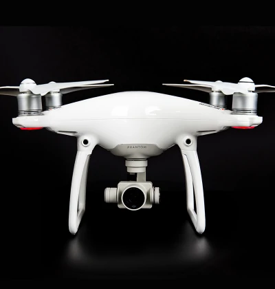

Aerospace & UAV
WJ Prototypes is your 3D manufacturing partner from prototype to large scale production.

Consumer Electronics
New Product Introduction Solutions for Consumer Electronics.

Robotics & Automation
Need some assistance bringing your robotic device or parts from the sketch-board to reality?

Medical Devices
The medical industry needs high quality, dependable and safe parts and products.

Automotive
New Product Introduction Solutions for Automotive

Industrial Machinery
The main purpose of industrial prototyping is to take the product from drawings into the real world.
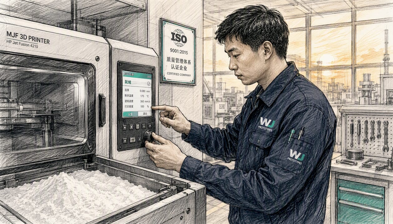

HP Multi Jet Fusion runs on six core material families, and knowing which one to reach for first saves real iteration time. PA12 is the default for most functional parts — strong, chemically resistant, and well-characterized. PA12 glass-filled (GB) steps in when you need stiffer, dimensionally tighter geometry. PA11 is the pick when ductility and impact toughness matter more than stiffness. Polypropylene handles chemical exposure and living-hinge designs. TPU and TPA cover flexible seals, gaskets, and wearable components. Specialty grades — flame-retardant PA12 FR and surface-enhanced PA12 S — address specific compliance and finish requirements. The HP materials portfolio covers all of these with per-material datasheets you should download before committing to a build.
Quick picks by use case:
Your next step after picking a family: pull the HP datasheet, cut tensile coupons per ASTM D638, and run a powder reuse qualification before committing to a production batch.
PA12 is the right starting point for most MJF projects — validate with ASTM D638 tensile coupons first, then switch material only when the coupon data identifies a specific property gap.
| Point | Details |
|---|---|
| PA12 is the default | Start functional prototypes in PA12; it balances tensile strength (~48 MPa), elongation (~20%), and chemical resistance. |
| Match material to the failure mode | Use PA11 for ductility and impact, PP for chemical resistance, TPU for flexible seals, PA12 GB for stiff tight-tolerance parts. |
| Run coupons before production | Print ASTM D638 tensile and ASTM D256 impact coupons in XY and Z orientations before committing to a production batch. |
| Qualify powder reuse | Track tensile results across reuse cycles; refresh powder based on qualification criteria. |
| WJ Prototypes for qualification builds | WJ Prototypes includes coupon geometry in the same MJF build batch and provides dimensional inspection reports for production traceability. |
MJF produces isotropic nylon parts with fine feature resolution and no support structures, which means the mechanical properties you measure in the Z-axis closely match X and Y. That isotropy is the single biggest reason engineers move functional parts from SLS to MJF. Here is what each material family actually delivers.

PA12 is the workhorse. Typical tensile strength runs around 48 MPa, elongation at break near 20%, and a Young’s modulus around 1,700 MPa. Heat deflection temperature (HDT) sits at roughly 175°C under 0.45 MPa load. Chemical resistance covers most oils, greases, and weak acids — not strong oxidizers or ketones. Surface finish out of the machine is matte gray; parts accept dye readily.
Minimum wall thickness: 1.0 mm for structural walls, 0.5 mm for thin features with support from surrounding geometry. Powder reuse sensitivity is moderate — most service bureaus run a 50/50 fresh-to-recycled blend as a starting point.
Common failure mode: stress whitening at sharp internal corners under cyclic load. Add a minimum 0.5 mm fillet radius at any stress concentration.
Glass bead filling increases stiffness and dimensional stability but reduces elongation and impact toughness, making PA12 GB the right call for jigs, fixtures, and housings where tight dimensions matter more than ductility. Tensile strength is comparable to PA12 at roughly 51 MPa, but modulus climbs to around 3,200 MPa. Elongation at break drops to approximately 8%, and notched Izod impact falls noticeably versus unfilled PA12.
HDT is similar to PA12. Chemical resistance profile is essentially the same. Surface finish is slightly rougher than PA12 due to the glass bead filler. Dyeing is possible but color uptake is less uniform. Powder reuse is more sensitive, so track reuse cycles carefully and qualify at each refresh.
Failure mode to watch: brittle fracture at thin walls under impact. Keep walls above 1.5 mm for load-bearing geometry in this material.
PA11 is bio-based (derived from castor oil) and noticeably tougher than PA12. Elongation at break can reach 40–50%, and impact resistance is substantially higher. Tensile strength is slightly lower, around 48 MPa, with a modulus near 1,600 MPa. HDT is comparable to PA12. The real advantage is fatigue resistance and ductility under dynamic loads — snap fits, living hinges, and parts that see repeated flex cycles hold up better in PA11.
Chemical resistance is good against hydrocarbons and many solvents. PA11 absorbs slightly more moisture than PA12, so dimensional stability in humid environments needs verification. Storage of PA11 powder requires tighter humidity control than PA12.
Application sweet spot: automotive interior clips, wearable device housings, and any part that needs to survive drop testing without cracking.
PP is the go-to when chemical resistance is the primary requirement. It resists most acids, bases, and solvents that would attack PA12. Tensile strength is lower — around 30 MPa — and modulus is around 800–900 MPa, so PP is not a structural material.
HDT is lower than PA12, typically around 100°C under load. PP parts are naturally white and semi-opaque. Dyeing is limited; painting requires surface preparation. Powder reuse behavior is more variable than PA12, and PP is more prone to warpage in large flat sections — design with ribs and avoid large unsupported spans.
PP is the right call for fluid-contact parts, lab consumables, and any assembly that will be exposed to cleaning agents or chemical sterilization.
Flexible MJF materials cover a range of shore harnesses. Lubrizol’s ESTANE 3D TPU M88A is a commonly referenced grade for MJF, offering good elongation and tear resistance. The ESTANE 3D TPU M95A provides a harder shore option for applications needing more structural integrity alongside flexibility.
TPU parts require careful shore hardness selection upfront — the difference between an 88A and a 95A part is significant in feel and function. Post-processing for TPU is more limited: aggressive bead blasting can distort fine features, and dyeing uptake varies by grade. Dimensional accuracy is lower than rigid materials; expect tolerances of ±0.5 mm or more on flexible geometry. Powder reuse for TPU is more restricted than PA12 and requires closer monitoring.
Use cases: seals, gaskets, over-mold simulations, grips, wearable straps, and vibration-damping mounts.
HP 3D HR PA 12 FR (enabled by Evonik) meets UL94 V-0 flame-retardant classification, making it the material of choice for electrical enclosures, connectors, and any assembly subject to UL or IEC flammability requirements. Mechanical properties are close to standard PA12, with some reduction in elongation. Confirm the specific UL file number against your application before production.
HP 3D HR PA 12 S (enabled by Arkema) is formulated for improved surface finish and is used where cosmetic quality or painting adhesion matters. Mechanical properties are broadly similar to PA12. It is the right pick when a part goes directly to a customer-facing assembly without heavy post-processing.
The table below maps each material family across the dimensions engineers use during trade-off analysis. Ratings of High / Medium / Low are relative within the MJF material set; numeric ranges are representative figures from HP and material-partner datasheets and should be confirmed against the specific grade datasheet before design sign-off.

Reading this table: tensile and modulus figures are representative mid-range values from HP and Lubrizol datasheets. Always run your own coupons before design freeze.
Selection strategy: start with PA12 for prototyping, validate with tensile and dimensional coupons, then switch material only when a specific property gap appears. Moving to PA11 for toughness or PP for chemical resistance is a targeted upgrade, not a default.
MJF’s supportless build process is genuinely freeing, but it does not eliminate the need for design discipline. These rules apply across most MJF materials; material-specific notes are called out where they differ.
Pro Tip: For threaded inserts in MJF parts, design a boss with a 0.2 mm oversize bore and use heat-set brass inserts rather than printing threads directly. Printed threads in PA12 hold adequately for light loads but strip under repeated assembly cycles.
Refer to the WJ Prototypes MJF technology guide for additional build-orientation and feature-size guidance specific to the HP Jet Fusion platform.
The standard sequence after a MJF build is: de-powdering → media blasting (bead or air) → optional dyeing, sealing, painting, or smoothing → secondary machining for critical dimensions. Each step has material-specific compatibility notes.
MJF’s as-built surface finish is already better than most SLS parts — typically Ra 8–12 µm before blasting, dropping to Ra 4–8 µm after bead blasting. That starting point means many functional parts ship without any additional finishing, which is a real cost advantage over processes that require mandatory post-processing for every part.
For post-processing options across MJF and other 3D printing materials, the material choice at the design stage determines which finishing paths remain open downstream.
MJF’s economics hinge on three variables: material cost per kilogram, powder reuse ratio, and packing efficiency. Getting all three right is what separates a cost-effective MJF run from an expensive one.
Primary cost drivers:
Powder reuse by material family:
Sustainability note: PA11’s castor-oil origin gives it a lower fossil-carbon footprint than PA12. The HP Jet Fusion 5200 platform supports PA11, PA12, PA12 S, PP, and TPU, with material handling systems designed to recover and recycle unfused powder.
Cost factor to adapt: if your build volume is 50% utilized and you switch from 30% to 50% recycled PA12 powder (after qualification), material cost per part drops proportionally to the fresh-powder fraction — a meaningful reduction on a 100-part run without changing geometry or machine time.
Both MJF and SLS build parts from polymer powder beds without support structures, but the engineering trade-offs between them are real and worth understanding before you commit a design to either process.
| Dimension | MJF | SLS |
|---|---|---|
| Build speed | Faster (full-width fusing agent pass) | Slower (laser traces each cross-section) |
| Isotropy | Higher (more uniform XYZ properties) | Moderate (Z slightly weaker) |
| Surface finish (as-built) | Ra 8–12 µm | Ra 12–20 µm |
| Material range | PA12, PA11, PP, TPU, FR grades | Broader (PA12, PA11, PEEK, TPE, glass-filled, ceramics) |
| Full-color capability | Yes (HP Multi Jet Fusion 5200 with color agent) | No |
| Part density | Higher (less porosity) | Moderate |
| Relative throughput cost | Lower at volume | Higher per part at volume |
| Legacy qualifications | Newer; fewer certified material files | Longer track record; more certified files in aerospace/medical |
MJF’s speed and isotropy advantage is most pronounced in mid-volume runs of 20–500 parts. Below that, setup cost differences narrow. Above that, injection molding economics typically take over.
When to pick MJF: functional prototypes needing isotropic properties, production runs of PA12 or PA11 parts, any job where color or surface finish matters, and projects where throughput cost is a constraint.
When SLS still fits: you need a material MJF does not currently support (PEEK, high-temp nylons, ceramic-filled grades), you have an existing SLS material qualification on file, or your application requires a certified material with a long regulatory history.
For a detailed side-by-side breakdown, the SLS vs MJF comparison for engineers covers build parameters, material behavior, and qualification considerations in depth.
Material qualification for MJF follows a staged workflow: datasheet review, lab coupon testing, environmental exposure, dimensional stability over reuse cycles, and production sampling. Here is a practical roadmap.
Staged validation workflow:
Suggested coupon dimensions and orientation:
Plot results on a control chart. Refresh powder when any batch falls below that threshold.
Pro Tip: Run one destructive tensile test and one non-destructive CT scan on the same build batch. CT scanning reveals internal porosity or incomplete fusion that tensile testing alone misses, especially in complex geometries. This combination catches process drift before it reaches customer parts.
The HP datasheet PDF (4AA7-7091ENW) includes detailed property tables and recommended post-processing notes that support this test plan.
At WJ Prototypes, material selection is not a one-time decision made at quoting — it is a structured process that runs through the first build, coupon testing, and at least one powder reuse cycle before a material is considered qualified for a client’s production run. Most projects start with PA12 because it is the most predictable, then shift to PA11 or PP when a specific property gap shows up in the coupon data. That sequence — prototype in PA12, validate the critical properties, upgrade material only when the data says so — avoids the common mistake of over-specifying a material before you know where the design actually fails.
For clients running low-volume production, WJ Prototypes documents each build batch, tracks powder reuse ratios, and provides dimensional inspection reports alongside the parts. That traceability matters when a part goes into an automotive or medical assembly and someone downstream needs to verify the material lot.
If you are at the material selection stage and want to run a trial build with test coupons before committing to a full production order, the fastest path is to submit your files for a quote and specify that you need a qualification build with coupon geometry included.
WJ Prototypes runs MJF builds alongside SLS, SLA, DMLS, and CNC machining under one ISO-certified roof, which means a material trial does not have to be a separate engagement from the production run that follows it.

For MJF specifically: submit print-ready files, specify your target material and finish, and WJ Prototypes returns a quote with lead time. Qualification builds include tensile and dimensional coupons printed in the same batch as your prototype geometry, so you get property data tied to the actual build conditions, not a generic datasheet. Finishing options — dyeing, sealing, painting, bead blasting — are available as part of the same order. For assemblies that combine MJF parts with machined metal features, CNC machining services run through the same quoting workflow.
Send your files or request a material consultation at Wjprototypes.
Download these resources before writing your material specification or qualification plan.
Download priority: start with the HP materials portfolio page to identify your grade, then pull the specific per-material datasheet. Add the HP technical document for machine-specific build guidance. For TPU, pull both Lubrizol TDS files and compare shore hardness options before specifying a grade.
Standard test methods to reference in your qualification documentation: ASTM D638 (tensile), ASTM D790 (flexural), ASTM D256 (Izod impact), ASTM D648 (HDT).
MJF material refers to the polymer powders compatible with HP’s Multi Jet Fusion 3D printing process. The main families are PA12, PA11, PA12 glass-filled, polypropylene, TPU/TPA, and specialty flame-retardant grades, each with distinct mechanical and thermal properties.
HP Multi Jet Fusion supports PA12 (the most common), PA11, PA12 glass-filled, polypropylene, TPU/TPA elastomers, and specialty grades including flame-retardant PA12 FR and surface-enhanced PA12 S. The full list with datasheets is available on the HP materials portfolio page.
MJF is generally faster, produces more isotropic parts, and delivers better as-built surface finish than SLS. SLS remains preferable when you need materials MJF does not support (such as PEEK or high-temperature nylons) or when an existing SLS material qualification is already on file for a regulated application.
MJF does not use filament. It is a powder-bed process: polymer powder is spread in layers, selectively fused using a fusing agent and an infrared energy source, then de-powdered after the build. The term “MJF filament” is a misnomer — the correct term is MJF powder or MJF material.
Choose PA12 when you need a well-characterized general-purpose material with good chemical resistance and predictable dimensional behavior.
SERVICES
RESOURCES