



- Room 1807, Unit 9, Building 2, Shangxing Commercial Street, Shangde Road, Shangxing Community, Xinqiao Subdistrict, Bao'an District, Shenzhen City, China
CONTACT US

WhatsApp


Contact Us
Our team is on stand by, waiting toassist you.

Videos
A large collection of educational videos and tutorials.

About Us
Learn about our company, leadership, and mission totransform manufacturing.

Privacy Policy
Applies to all personal information collected through and/or processed in connection.


Aerospace & UAV
WJ Prototypes is your 3D manufacturing partner from prototype to large scale production.

Consumer Electronics
New Product Introduction Solutions for Consumer Electronics.

Robotics & Automation
Need some assistance bringing your robotic device or parts from the sketch-board to reality?

Medical Devices
The medical industry needs high quality, dependable and safe parts and products.

Automotive
New Product Introduction Solutions for Automotive

Industrial Machinery
The main purpose of industrial prototyping is to take the product from drawings into the real world.
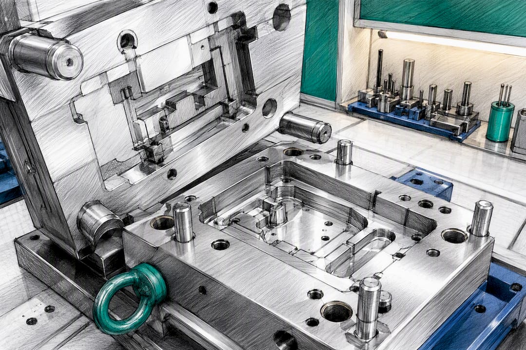
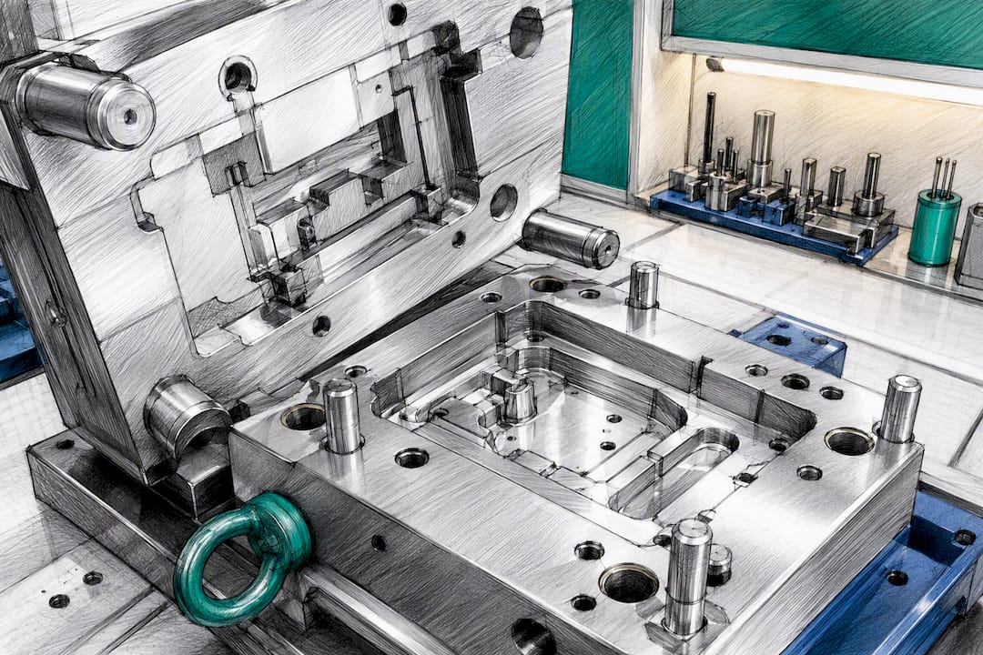
Most undercuts can be designed out or swapped for cheaper tooling elements, and doing so is usually the single biggest lever you have over mold cost. Start with three moves: reorient the part or shift the split line so the feature drafts out naturally, consolidate redundant holes and ribs into standard sizes, and validate the fix with a low-cost print or soft-tool sample before cutting steel. Engineers who apply this discipline early routinely see tooling quotes drop into a significant savings range, and WJ Prototypes has walked clients through exactly this process on production molds bound for China.
TL;DR:
Reorient the part or shift the split line to eliminate most undercuts without additional tooling mechanisms, saving significant mold costs from the outset.
Standardizing hole sizes, adding adequate draft, and unifying wall thicknesses can reduce tooling complexity and cycle time, lowering per-part expenses.
Removing or redesigning undercuts early, rather than relying on side-actions, typically results in lower total costs and shorter lead times across production runs.
Specifying the correct steel grade, cavity count, and clear functional constraints in RFQs ensures more accurate quotes and avoids costly design assumptions.
Low-cost validation methods like 3D-printed cores or soft tooling help identify potential fill or ejection issues before committing to steel, reducing rework and scrap.
Most of a product's manufacturing cost gets locked in during design, long before a supplier ever quotes a mold. That is the uncomfortable truth behind every "why is my tooling so expensive" conversation: by the time a part reaches a Chinese toolmaker for quoting, most of the cost decisions have already been made on the CAD screen. A design-to-cost case study using activity-based costing found an 18 percent unit cost reduction simply from folding cost analysis into early design reviews, rather than treating it as a post-quote negotiation.
Tooling cost drivers break down into a short list, and most engineers underestimate at least two of them:
Here is where most quoting conversations go wrong: teams compare mold price quotes instead of cost-per-part. A tool that costs 20 percent less upfront but runs a longer cycle or needs more manual labor per shot can lose that savings within the first few thousand units. MSC Industrial Supply's analysis of tooling ROI makes the same point from the cutting-tool side: tooling decisions have to account for cycle time, scrap rate, and uptime, not just the number on the quote.
An undercut is any feature that blocks the mold from opening in a straight line, forcing the tool to use a slide, lifter, or collapsible core to free the part. That single design condition is responsible for a large share of tooling cost overruns, because each mechanism adds machining time, wear points, and a maintenance schedule the customer eventually pays for.
The usual suspects show up in almost every CAD file:
Beyond the undercut itself, tolerance choices and hole variety quietly drive tool-change costs. A design with a dozen different hole diameters forces a dozen different drill or EDM operations; standardizing those into three or four sizes can save several dollars per part in reduced tool changes and setup time, which compounds fast across a production run.
A few concrete thresholds are worth checking before you send a file out for quoting: draft angles below 1 to 2 degrees on vertical walls invite scuffing and ejection failure; internal radii tighter than half the wall thickness create stress risers and cooling problems; wall thickness variation beyond a 3:1 ratio between thick and thin sections causes sink marks and warping that no amount of tooling skill can fix downstream.
Pro Tip: Run a "pull direction" check on every feature in your CAD model before the file leaves your desk. Color-code anything that does not draft cleanly in the primary open direction. That five-minute pass catches most undercuts before a supplier ever sees the drawing.
Removing an undercut almost always beats engineering around it, because a redesign costs nothing to run in production while a slide or lifter costs money on every single cycle for the life of the tool. The ejection and shutoff benefits of a clean design show up directly in simplified mold construction and fewer wear points.
Four tactics solve the majority of undercut problems:
Pro Tip: Before choosing between redesign and tooling complexity, ask three questions: does the feature carry a real functional load, does the part run in high volume, and is the redesign visible to the end customer? If the answer to all three is no, redesign almost always wins.
The decision rule engineers skip most often: compare the one-time engineering cost of a redesign against the recurring cost of a slide across the full production run, not just the tooling quote. A side-action might add several thousand dollars to a mold budget and slow every cycle by a few seconds. Multiply that cycle penalty across a typical production run and the redesign usually wins outright, even when it takes a few extra design revisions to get right.
Not every undercut is worth eliminating, and China's toolmaking ecosystem offers a range of mechanisms that fit different production realities. Knowing which one to specify, and how to ask for it, keeps quotes honest.
When you send an RFQ to a Chinese supplier, specify steel grade (P20 versus H13 changes both price and expected shot life), expected cavity count, and where you want T1 sample inspection gates. Vague specs are the single biggest reason quotes come back inconsistent between suppliers, because each toolmaker fills in the gaps with their own assumptions about mechanism choice and steel quality.
Moldflow or an equivalent simulation earns its cost when you point it at a specific risk, not when you run it as a generic checkbox. Target it at fill pattern, knit line location, and ejection force on any feature near an undercut, since simulation is most valuable when it validates a specific ejection or fill risk rather than serving as a broad, unfocused study.
Before committing to steel, three lower-cost validation paths catch problems simulation alone can miss:
Statistic Callout: Early cost-integration reviews, including simulation-driven design checks, have produced unit cost reductions near 18 percent in documented case studies, largely by catching ejection and fill problems before steel is cut rather than after.
A reasonable confidence threshold before releasing to tooling: the simulation shows no unresolved short-shot or knit-line risk near critical surfaces, and any prototype sample matches the CAD model within your functional tolerance on the features that matter most.
Run this list before any file leaves your desk for quoting. It is ordered by effort versus payoff, cheapest fixes first.
| Fix | Effort | Typical payoff |
|---|---|---|
| Consolidate hole sizes | Low | Several dollars per part in setup savings |
| Add draft to vertical walls | Low | Fewer ejection failures, lower scrap |
| Reorient part to remove undercut | Medium | Eliminates a slide or lifter entirely |
| Split assembly instead of tooling a slide | Medium to high | Trades tool cost for a onetime assembly step |
Picture a housing with a snap tab molded into a side wall, needing a lifter. Reorient the part so the tab points toward the main draw, and the same feature molds with a two-plate tool. The mold gets simpler, the cycle gets shorter, and the fix costs a design revision instead of a tooling line item.
The pattern repeats across nearly every project our engineers review: a client arrives with a slide or lifter already specified, and half the time the feature can be reoriented or split into a simpler assembly before it ever reaches steel. The other half genuinely needs the mechanism, and that is fine. The job is telling the two apart early.
A snap-fit enclosure redesigned to drop a single side-action lifter typically simplifies mold construction enough to shorten lead time and reduce long-term maintenance exposure, without changing the part's function at all.
When you request a DFM review from WJ Prototypes, send the native CAD file, your target production volume, and any functional constraints on the features you suspect are undercuts. That context lets our team flag redesign opportunities before quoting, not after.
Most DFM advice treats undercut elimination as a step that happens after a mold quote comes back too high. That sequencing is backwards, and it is the biggest gap between conventional advice and what actually works. By the time a quote lands on your desk, the toolmaker has already priced the slide you never questioned.
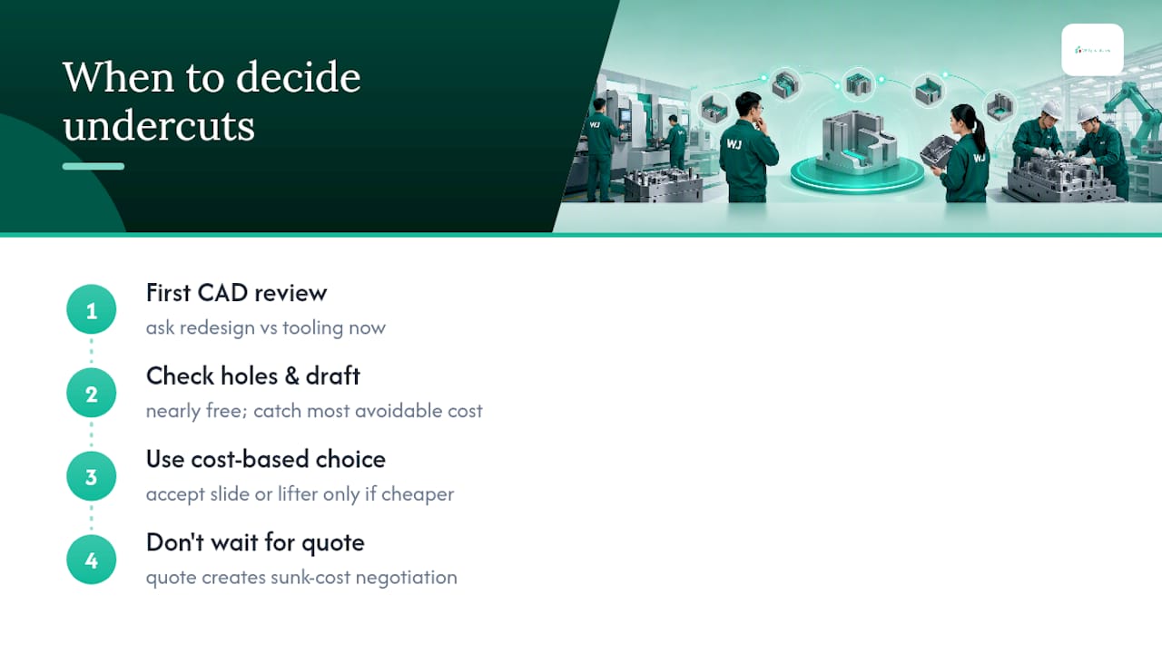
The redesign-versus-tooling-complexity decision belongs in the first CAD review, not the negotiation phase. Engineers who wait for the quote to flag a problem are negotiating against a sunk cost: the supplier has already engineered around your undercut, and asking them to requote a simplified geometry after the fact slows the whole program down.
What the evidence in this article actually supports is narrower than most guides admit: not every undercut needs elimination, and chasing a zero-slide design on a low-volume, high-value part can cost more in engineering hours than the tooling savings justify. The discipline that pays off is asking the redesign question early and consistently, then accepting a slide or lifter when the numbers say it is genuinely cheaper. Prioritize the hole consolidation and draft angle checks first. They are nearly free and they catch most of the avoidable cost before anyone even talks about tooling.
— Nas
If your CAD file has an undercut you are not sure is worth keeping, WJ Prototypes can tell you before steel gets cut instead of after. We run CNC machining and vacuum casting first articles to validate tricky geometry cheaply, then move straight into low-volume or full-production tooling once the design is proven.
Send your native CAD file, target volume, and any functional constraints on suspected undercut features, and you will get a DFM review flagging redesign opportunities alongside your tooling quote, not buried inside it. If you need a machined alternative while the mold design settles, our CNC machining materials page covers what qualifies for both prototyping and short-run production. Submit your files through our instant quote system to get started and see where your part actually stands before committing to a full production mold.
Roughly most of total manufacturing cost is locked in during the design phase, before a mold ever gets quoted, which is why early DFM reviews return the largest savings.
No. Many undercuts can be removed by reorienting the part or converting negative geometry to positive, but functional features on high-value parts sometimes justify a slide or lifter instead.
A minimum of 1 to 2 degrees of draft on vertical walls generally prevents scuffing and ejection failure, with more draft needed on textured surfaces.
Standardizing hole and fastener sizes down to three or four diameters can save several dollars per part through reduced tool changes and setup time.
Run simulation when you need to check fill pattern, knit lines, or ejection force on a specific feature; use soft tooling or 3D printed cores when you need to physically confirm a tricky undercut behaves as predicted.
Submit your native CAD file, target production volume, and functional constraints on suspected undercut features through the WJ Prototypes instant quote system to receive a DFM review alongside your tooling quote.
Setting Tolerances Without Overpaying for Chinese Mold Tooling
China Vs US Prototyping: Cost Breakdown Saving 41%
From CAD to Component: Inside Shenzhen's Tooling Ecosystem
SERVICES
RESOURCES