



- Room 1807, Unit 9, Building 2, Shangxing Commercial Street, Shangde Road, Shangxing Community, Xinqiao Subdistrict, Bao'an District, Shenzhen City, China
CONTACT US

WhatsApp


Contact Us
Our team is on stand by, waiting toassist you.

Videos
A large collection of educational videos and tutorials.

About Us
Learn about our company, leadership, and mission totransform manufacturing.

Privacy Policy
Applies to all personal information collected through and/or processed in connection.


Aerospace & UAV
WJ Prototypes is your 3D manufacturing partner from prototype to large scale production.

Consumer Electronics
New Product Introduction Solutions for Consumer Electronics.

Robotics & Automation
Need some assistance bringing your robotic device or parts from the sketch-board to reality?

Medical Devices
The medical industry needs high quality, dependable and safe parts and products.

Automotive
New Product Introduction Solutions for Automotive

Industrial Machinery
The main purpose of industrial prototyping is to take the product from drawings into the real world.
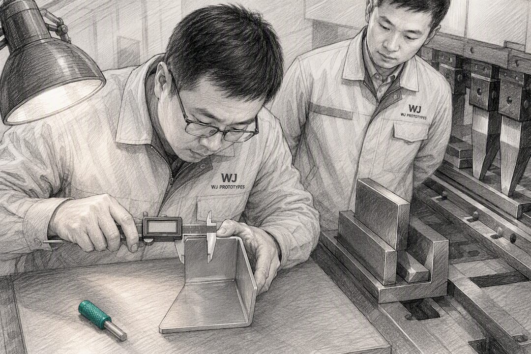

K-factor is the ratio between the neutral axis offset and material thickness (K = d/t), and it drives how much metal a flat pattern needs at every bend. The single move that prevents rework: never trust CAD software defaults like 0.44 or 0.5 on a production release. Get a shop-calibrated K-factor, or put explicit bend deduction values on the drawing, before your fabricator cuts a single blank.
TL;DR:
- Using a shop-calibrated K-factor significantly improves bend accuracy; relying on default CAD values or charts without testing leads to errors.
- Testing at least three coupons per material and tooling combination ensures reliable K-factor calibration and accounts for measurement variability.
- K-factor varies with material grade, thickness, tooling, bend radius, and forming method, making it essential to calibrate for each specific setup.
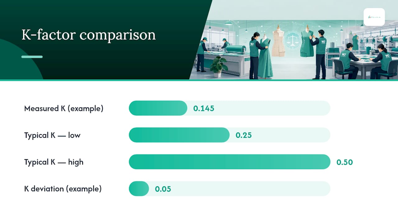
- Ranges from about 0.25 to 0.50 are typical, but actual K-values must be measured; approximation from charts is only a starting point.
- CAD software often hides the true K-factor, so verifying or overriding it during the design review process prevents hidden errors from propagating into production.
Every bend in sheet metal stretches the outer surface and compresses the inner one. Somewhere in between sits a layer that neither stretches nor compresses: the neutral axis. K-factor describes exactly where that layer sits, expressed as a ratio of the distance from the inside bend surface (d) to the total material thickness (t). Write it as K = d / t, and you have the single number that determines how long your flat blank needs to be.
That number feeds directly into the bend allowance formula: BA = θ (R + Kt), where θ is the bend angle in radians, R is the inside bend radius, and t is material thickness. Bend allowance is the arc length added at the bend, measured along the neutral axis. Get K wrong by even a little, and every flange on the part comes out the wrong length.
Three terms get mixed up constantly, and the confusion causes real errors. Bend allowance (BA) is the length of material consumed by the bend itself, measured along the neutral axis. Bend deduction (BD) is a different animal: it is the amount you subtract from the sum of the two flange lengths (measured to the outside mold line) to get the correct flat length. K-factor is the input variable that lets you calculate BA in the first place. Fabricators sometimes hand you a BD directly instead of a K value, and mixing the two into the same calculation produces a part that is wrong in a predictable, avoidable way.
Measurement convention matters just as much as the math. Flange lengths get measured either to the tangent point (where the flat wall ends and the bend radius begins) or to the outside mold line (where two flange planes would theoretically intersect if extended). CAD software defaults to one or the other depending on the modeling method, and mismatching your hand calculation against the software’s convention is a quiet, common source of dimensional drift.
K-factor typically ranges from about 0.25 to 0.50, and that range is not a material constant. It shifts with thickness, radius, tooling, and forming method, which is precisely why a value borrowed from a textbook or a different job rarely survives contact with a real press brake. Near 180 degree bends (hems and tight folds), the math gets less reliable, and shops typically handle those with dedicated tooling and empirical allowances rather than the standard BA formula.

Back-calculating K-factor from a physical test coupon is the most reliable path to a number you can trust, and the math takes minutes once you have the measurements.
Here is a worked example. Take a 90 degree bend in 0.060 inch mild steel with a 0.060 inch inside radius. Suppose your coupon measurements yield a bend allowance of 0.108 inch. Convert 90 degrees to radians (1.5708). Then K = (0.108 / 1.5708 − 0.060) / 0.060, which works out to K ≈ 0.145. That looks low against the typical 0.25 to 0.50 range, so before accepting it, double-check your BA measurement and radius reading. Small measurement errors near tight radii distort the back-calculated K disproportionately, which is exactly why shops run several coupons rather than one.
Errors compound fast on multi-bend parts. A K-factor deviation of just 0.05 can shift flange length enough per bend that a four-bend bracket ends up with hole locations off by a visible margin. Treat coupon testing as a tolerance-control step, not a one-time formality, especially on parts with more than two bends feeding into a critical dimension.
K-factor is not a fixed material property. It is a calibration constant that shifts with the physical setup of the bend, and treating it as a lookup number instead of a measured one is where most flat pattern errors start.
The radius-to-thickness ratio (R/t) is the biggest driver. As R/t increases, meaning the bend radius grows large relative to material thickness, K trends upward toward the higher end of its range. Tight radii relative to thickness push K lower, because a larger proportion of the material near the bend deforms plastically rather than elastically.
Material behavior matters almost as much. Ductile, dead-soft aluminum behaves differently under the same tooling than a full-hard stainless sheet. Higher yield strength and lower elongation typically shift the neutral axis and change how much the material springs back after the punch retracts.
Tooling and forming method change K independently of material:
Grain direction, lubrication, springback behavior, and coating thickness all nudge the number further. A galvanized or pre-plated sheet bends slightly differently than bare cold-rolled stock of the same nominal thickness, and bending across the grain versus with it changes crack risk and, in marginal cases, the measured bend allowance.
Pro Tip: If you’re reusing a K-factor from a previous job, check whether the material grade, thickness, tooling, or forming method changed even slightly. Any one of those four variables invalidates the old calibration.
A radius-to-thickness chart gives you a defensible starting point when no coupon data exists yet, and it beats guessing. It is not a substitute for a measured value on a released production part.
| R/t Ratio | Typical Starting K-Factor Range |
|---|---|
| Up to 1 | 0.30 to 0.35 |
| 1 to 2 | 0.35 |
| 2 to 4 | 0.40 |
| Greater than 4 | 0.45 |
These bands come from accumulated shop data across common materials and thicknesses, and they work well for early design iterations, quoting rough part cost, and sanity-checking a value a fabricator quotes back to you. What they cannot do is account for your specific tooling, your specific material lot, or your specific forming method, all of which shift the real number within (and sometimes outside) that band.
Mark any chart-derived K-factor as provisional directly in the CAD model, in a custom property field or a drawing note. That flag tells the next engineer who opens the file, and the fabricator reading the drawing, that this number has not been validated against a physical part yet. Charts are a reasoned starting value; they are not a validated process record, and treating them as final on a released drawing is how flat pattern errors slip into production undetected.
Any part with a critical hole pattern, a tight tolerance stack, or more than two bends feeding a single dimension should skip the chart entirely and go straight to a test coupon before you release for production.
CAD software makes K-factor invisible in a way that causes real damage. The number lives buried in document properties or a sheet metal feature override, and it is easy to release a part without ever seeing what value actually got used.
Different CAD kernels handle unfolding math differently, so migrating a part between systems, or even between major software versions, can shift the flat pattern by a small but real amount even with identical K-factor settings entered. Re-verify after any migration; do not assume the old flat pattern is still correct.
Pro Tip: Build a shared team template with your validated K-factors and gauge tables pre-loaded, so no one on the team is quietly working off the software’s factory default. Standardizing this at the template level, paired with a part-review checkpoint before release, catches the majority of these errors before a drawing ever leaves your building. The sheet metal fabrication workflow your parts follow downstream depends entirely on getting this step right upstream.
Getting a clean first article from a fabricator overseas comes down to a repeatable coupon protocol and a short, specific data exchange, not a long specification document.
Run at least three test coupons per material lot and thickness combination, bent on the actual tooling and forming method the production job will use, not a substitute setup. Measure each coupon independently and average the results; a single coupon carries no way to catch a measurement fluke. Inspect angle with a digital protractor and flange length with calipers referenced to the same tangent point convention you used in CAD.
A defensible calibration record includes:
That calibrated K-factor applies only to the exact combination that produced it: same material lot, same thickness, same tooling, same method. Change any one variable and the number needs re-validation. Your drawing or DXF should carry the K-factor or BD value directly, the measurement convention used, the finished inside radius, and an inspection datum the fabricator can check the first article against, exactly the kind of documentation covered in a solid sheet metal fabrication guide. Before cutting begins, confirm in writing what tooling and forming method the shop plans to use, since a fabricator switching from air bending to bottoming without telling you invalidates your calibration silently.
Run this sequence before releasing any sheet metal part for production cutting:
When a finished part comes back wrong, check geometry first: confirm angle and radius before you touch K-factor, since a tooling or measurement mismatch causes the same symptoms as a bad K value. Stop production immediately if flange length is off by more than your tolerance band, if the coupon angle does not match the drawing, or if the fabricator reports a tooling substitution mid-run.
Pro Tip: Keep a one-page calibration log per material and thickness combination. The five minutes it takes to check a past record against a new job beats re-deriving K-factor from scratch every time.
Getting flat patterns right the first time is a process problem before it is a math problem, and that’s the lens WJ Prototypes brings to every sheet metal job. As an ISO-certified manufacturer, we run test coupon protocols on the actual production tooling and material lot for every new part, then hand back a documented, back-calculated K-factor rather than asking an engineer to trust a chart or a CAD default.
That protocol looks a lot like the process outlined above: multiple coupons, measured angle and flange length, a recorded material grade and thickness, and a calibration file the engineering team can review before committing to a full run. To engage, send your drawing or model with target material, thickness, and bend geometry, and expect a coupon evaluation and calibration report ahead of first-article production.
— Nas
WJ Prototypes replaces the guesswork this article just walked you through with an actual coupon-tested calibration record for your specific job. Instead of hoping a CAD default or a chart value survives contact with a real press brake, you get a documented K-factor or bend deduction value tied to your material lot, thickness, and tooling before production starts.

That matters most for engineers coordinating sheet metal parts with fabricators overseas, where a single miscommunicated K-factor can mean a wasted shipment and weeks of delay. Our ISO-certified process runs test coupons on your specified sheet metal materials and forming method, then documents the calibration before your production blanks get cut. If your part serves aerospace, automotive, or industrial machinery applications where tolerance stack-up matters, that documentation becomes part of your quality record, not an afterthought.
Ready to stop guessing at bend allowance? Submit your drawing and specs through our CNC machining and sheet metal quoting page to get a coupon evaluation and calibrated K-factor before your next production run.
For R/t ratios up to 1, start in the 0.30 to 0.35 range, but treat it as provisional until a test coupon confirms the value on your actual tooling.
The most common cause is a document-level K-factor default like 0.44 or 0.5 still active in the CAD file instead of a shop-calibrated value, often compounded by a mismatched measurement convention.
No. K-factor is an input variable used to calculate bend allowance, while bend deduction is the value subtracted directly from total outside flange lengths to get flat length; they solve the same problem differently.
Bend at least three coupons per material lot, thickness, and tooling combination, since a single coupon cannot catch a measurement error or an outlier bend.
Yes, WJ Prototypes runs coupon-based calibration on the specified material and tooling and documents the resulting K-factor or bend deduction as part of first-article production, rather than relying on default CAD values.
SERVICES
RESOURCES