



- Room 1807, Unit 9, Building 2, Shangxing Commercial Street, Shangde Road, Shangxing Community, Xinqiao Subdistrict, Bao'an District, Shenzhen City, China
CONTACT US

WhatsApp


Contact Us
Our team is on stand by, waiting toassist you.

Videos
A large collection of educational videos and tutorials.

About Us
Learn about our company, leadership, and mission totransform manufacturing.

Privacy Policy
Applies to all personal information collected through and/or processed in connection.


Aerospace & UAV
WJ Prototypes is your 3D manufacturing partner from prototype to large scale production.

Consumer Electronics
New Product Introduction Solutions for Consumer Electronics.

Robotics & Automation
Need some assistance bringing your robotic device or parts from the sketch-board to reality?

Medical Devices
The medical industry needs high quality, dependable and safe parts and products.

Automotive
New Product Introduction Solutions for Automotive

Industrial Machinery
The main purpose of industrial prototyping is to take the product from drawings into the real world.
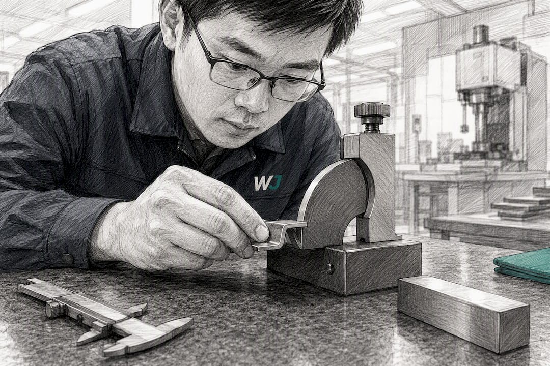

K-factor is the ratio of the neutral axis offset to material thickness, and it’s the multiplier you plug into the bend allowance formula to compute accurate flat patterns. Most shops start from a default around 0.446, but the real number shifts with tooling, material, and forming method, which is why calibrating it against your own press brake matters more than trusting a CAD default.
TL;DR:
- The actual K-factor varies significantly with tooling setup, material, and forming method, making calibration with test bends essential for accuracy.
- Test bends should be performed multiple times, measuring bend allowances and radii precisely to determine a reliable K-factor for each material and machine combination.
- Typical K-factor ranges from 0.30 to 0.50, with mild steel averaging around 0.446, but actual values should be confirmed through experimentation.
- Changes in die opening, punch radius, or press brake setup can alter the K-factor, so recalibration is necessary when switching tools or materials.
- Building a detailed K-factor database with metadata ensures consistent, accurate flat pattern development across different jobs and setups.
Every time you bend a sheet of metal, the outer surface stretches and the inner surface compresses. Somewhere in between sits a plane that does neither. That’s the neutral axis, and it doesn’t sit at the exact geometric center of the material once the bend happens. It shifts slightly toward the inside surface, and how far it shifts determines how long your flat blank needs to be before forming.
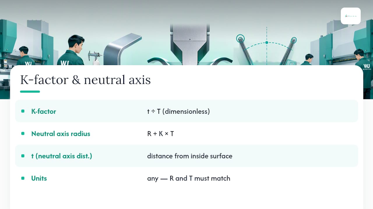
The K-factor is defined as t divided by Mt, where t is the distance from the inside surface of the material to the neutral axis, and Mt is the total material thickness. Expressed as a location, the neutral axis radius equals R + K × T, where R is the inside bend radius and T is the material thickness.
You can visualize this by sketching a cross section of a 90 degree bend: draw the inside radius arc, draw the outside radius arc, and mark a third arc somewhere between them where fiber length stays unchanged before and after forming. That third arc is what K locates. Units don’t matter here since K is dimensionless. It works the same whether you’re calculating in inches or millimeters, as long as R and T use matching units.
Once you know K, three formulas do the heavy lifting for flat pattern development. Each builds on the last.
Bend allowance (BA) is the length of material consumed by the bend, measured along the neutral axis:
BA = (π/180) × θ × (R + K × T)
Here, θ is the bend angle in degrees, R is the inside radius, T is material thickness, and K is your neutral axis offset factor. The π/180 term simply converts degrees into radians so the arc length math works out correctly. This equation comes straight from ToolGrit’s flat pattern development guide, and it’s the one formula every sheet metal designer eventually memorizes.
Outside setback (OSSB) is the distance from the bend’s outer tangent line to the apex of the bend, calculated as:
OSSB = tan(θ/2) × (R + T)
Bend deduction (BD) tells you how much shorter the flat blank needs to be compared to the sum of the outside flange dimensions:
BD = 2 × OSSB − BA
Here’s how these fit together in practice:
Quick math check: for a 90 degree bend in 0.060 inch mild steel with a 0.060 inch inside radius and K = 0.446, BA works out to (π/180) × 90 × (0.060 + 0.446 × 0.060) = 1.5708 × 0.0868 ≈ 0.136 inches. That’s the arc length your flat pattern needs to account for at that single bend line.
CAD software will hand you a default K-factor whether you ask for it or not. The only way to know if that number matches your actual press brake, die, and material lot is to run a test bend and work the math backward. This is the method The Fabricator recommends for shops that need production-accurate bend tables instead of textbook guesses.
Worked example: Say your 4.000 inch coupon in 0.075 inch aluminum forms a 90 degree bend with measured leg lengths totaling 4.062 inches after subtracting the outside setback geometry, giving you a BA of 0.118 inches. Your inside radius measures 0.090 inches. Plugging in:
K = [(0.118 / (1.5708)) − 0.090] / 0.075 = [(0.0751) − 0.090] / 0.075 = −0.0149 / 0.075
That negative result signals a measurement or setup error, which is exactly the point of running the math yourself rather than trusting a single reading. Real test bends typically land K somewhere between 0.30 and 0.50, and if your calculation falls outside that band, remeasure before you commit the number to a bend table.
Pro Tip: Run three to five repeats of the same bend before you trust a K value. Press brake tonnage drift, material lot variation, and even ambient temperature can shift your result by a few hundredths, and averaging repeats catches that noise.
Published K-factor ranges give you a starting point for test bends, not a number to skip testing altogether. Values typically span 0.30 to 0.50, with the position inside that range driven by forming method and material behavior.
Treat every one of these as a starting value for your first test coupon, not a number you carry into production tooling. A K-factor chart tells you where to point your first test bend. Your press brake tells you the real answer.
K-factor isn’t a fixed material constant, it’s a process outcome. The same aluminum sheet can produce two different K values on two different press brakes, and understanding why keeps you from chasing phantom dimensional errors.
Pro Tip: If you change punches, dies, or press brakes for a job you’ve run before, don’t assume last year’s K-factor still applies. Rerun the test coupon. A 0.02 shift in K on a long flange adds up fast across multiple bends.
A single test bend gives you one data point. A usable K-factor database gives you a reference you can trust across jobs, materials, and machines. Building one takes discipline, but it’s the difference between guessing and knowing.
Start with a test plan that varies the variables that matter most: run coupons at two or three die openings per material thickness, and repeat each combination at least three times. This isolates die opening as a variable instead of burying it inside a single averaged number. Measure formed dimensions with an optical comparator or calibrated radius gauges rather than a standard caliper, since bend radius measurement error compounds directly into your calculated K.
Every K value you record needs metadata attached, or it becomes useless six months later:
Once you’ve got a reliable K, update your CAD bend tables with the material and thickness combination tied to that specific tooling setup, not a generic sheet metal default. Recalibrate whenever you change press brakes, switch die vendors, or start a new material lot from a different mill, since chemistry and temper variation between lots can shift bending behavior even within the same nominal spec.
| What to track | Why it matters |
|---|---|
| Die opening and punch radius | Directly shifts inside radius and K |
| Material lot/heat number | Chemistry and temper vary between lots |
| Press brake ID | Tonnage and ram parallelism differ machine to machine |
| Bend angle and measured radius | Confirms the test conditions match production |
| Date and operator | Flags when to rerun calibration |
Version your bend tables the same way you’d version a drawing. A K-factor tied to “Press 3, Die Set B, 304 stainless, lot #4471” tells the next engineer exactly what conditions produced that number, and whether it still applies to their job.
Y-factor is a refinement of K that accounts for the fact that material doesn’t behave perfectly linearly through the bend. The relationship is Y = π/2 × K, and some CAD packages use Y instead of K internally even though they display K to the user.
CAD systems often interpolate K rather than using one fixed value across every bend. BricsCAD’s approach, for example, adjusts K based on the ratio of inside radius to thickness (R/T): tighter radii relative to thickness pull K toward a lower value, while R/T ratios of 4 or higher push K toward 0.5.
Before you trust any CAD bend table, check these fields:
The chart values in this guide are a starting line, not a finish line. Every fabricator who’s chased a flat pattern error back to its source eventually lands on the same lesson: K-factor is a property of your press brake and your die, not just your material. Skipping the test bend to save twenty minutes costs a lot more than that when a production run comes back out of tolerance.
Document every calibration the same way, every time. Future you will thank present you.
— Nas
For deeper formula derivations and CAD interpolation logic, see The Fabricator’s press brake precision guide, ToolGrit’s bend deduction guide, and BricsCAD’s K-factor documentation.
If your next project needs flat patterns built around a calibrated bend table rather than a generic assumption, a professional prototyping service can work from your specified material and tooling data to produce accurate sheet metal parts. Browse available sheet metal materials or get a quote through the CNC machining materials page if your part mixes formed sheet metal with machined features.
K-factor is the ratio of the neutral axis offset (distance from the inside surface to the neutral axis) to the total material thickness. It typically ranges from about 0.30 to 0.50 depending on material, forming method, and tooling.
You determine K-factor by bending a test coupon, measuring the resulting leg lengths and inside radius, then working backward through the bend allowance formula to solve for K. Running three to five repeats and averaging the results improves accuracy over a single measurement.
Rearrange the bend allowance formula to isolate K: K = [(BA / (π/180 × θ)) − R] / T, using your measured bend allowance, bend angle, inside radius, and material thickness. This calculation only works with real measured data from a test bend, not assumed values.
Start from a default of about 0.446 for general air bending in mild steel, but treat that as a starting point only. Your actual K depends on your specific die opening, punch radius, material, and press brake, and should come from a calibrated test bend rather than a chart alone.
SERVICES
RESOURCES