


- Room 1807, Unit 9, Building 2, Shangxing Commercial Street, Shangde Road, Shangxing Community, Xinqiao Subdistrict, Bao'an District, Shenzhen City, China
CONTACT US

WhatsApp

Aerospace & UAV
WJ Prototypes is your 3D manufacturing partner from prototype to large scale production.
Consumer Electronics
New Product Introduction Solutions for Consumer Electronics.

Robotics & Automation
Need some assistance bringing your robotic device or parts from the sketch-board to reality?
Medical Devices
The medical industry needs high quality, dependable and safe parts and products.
Automotive
New Product Introduction Solutions for Automotive
Industrial Machinery
The main purpose of industrial prototyping is to take the product from drawings into the real world.

Over 60% of British and American manufacturers report that material selection and precise design requirements drive success in rapid prototyping. For North American aerospace and automotive engineers, every decision in the sheet metal fabrication process—from CAD modeling to quality inspection—affects timelines and costs. This guide highlights the practical steps and technical considerations that help you achieve reliable, high-performance prototypes for low-volume production.
| Key Point | Explanation |
|---|---|
| 1. Define requirements and select materials | Understanding engineering needs and choosing suitable materials is crucial for optimal design performance. |
| 2. Prepare accurate CAD models and set tolerances | Use professional CAD tools to create detailed models and define tolerances for precise manufacturing. |
| 3. Set up tooling and machinery effectively | Ensure proper setup of machines and tools to align with project requirements for enhanced production quality. |
| 4. Execute precise operations with careful control | Perform cutting, bending, and forming with attention to detail to maintain design integrity and component accuracy. |
| 5. Conduct thorough inspections and finishing | Verify dimensions and finish components to confirm they meet quality standards before assembly and testing. |
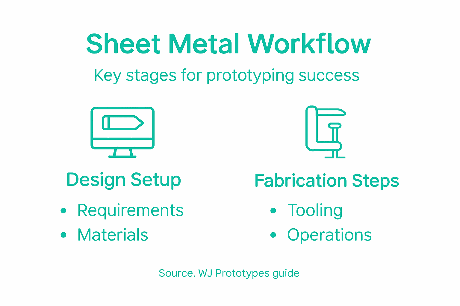
Defining precise design requirements and selecting appropriate materials are foundational stages in sheet metal fabrication for prototyping. These initial steps determine the overall performance and manufacturability of your final product.
Starting with design requirements involves understanding your specific engineering needs and constraints. You will need to analyse dimensional tolerances, structural integrity, functional performance and anticipated manufacturing processes. Manufacturability considerations include evaluating potential fabrication techniques such as cutting, punching, stamping and bending. Critical parameters like material thickness, bend radii, hole sizes and geometric complexity must align with standard sheet metal fabrication capabilities.
Material selection demands careful evaluation of mechanical properties. Carbon steel, stainless steel and aluminium represent common choices, each offering distinct advantages. Stainless steel provides superior corrosion resistance, aluminium offers lightweight strength, while carbon steel delivers cost effectiveness. Your selection should balance strength requirements, weight considerations, environmental exposure and budget limitations.
When choosing materials, consider these key performance attributes:
Here is a comparison of commonly used sheet metal materials and their key properties:
| Material | Strength Characteristics | Corrosion Resistance | Typical Applications |
|---|---|---|---|
| Carbon Steel | High tensile strength | Poor without coating | Structural parts, brackets |
| Stainless Steel | Moderate to high strength | Excellent | Medical devices, food equipment |
| Aluminium | Lightweight, moderate strength | Good with treatments | Aerospace, automotive panels |
Top Engineering Tip:Always prototype with materials that closely match your final production material to validate design performance and manufacturability.
Preparing accurate CAD models and defining precise tolerances are critical steps in transforming design concepts into manufacturable sheet metal prototypes. These processes ensure your digital design translates seamlessly into physical components.
Begin by leveraging professional CAD tools for sheet metal design, such as SolidWorks or Inventor. These sophisticated software platforms enable engineers to apply Design for Manufacturability (DFM) principles, which help optimise designs for efficient production. When developing your model, maintain uniform material thickness and focus on creating geometric features that align with standard fabrication capabilities.
Establishing tolerances requires meticulous attention to detail. Typical tolerance ranges include ±0.005 inches for linear dimensions and ±0.020 inches for forming and bending processes. Your CAD model should communicate critical dimensions explicitly, ensuring manufacturers can reproduce your design with high precision. Key considerations include:
Model Based Definition techniques can help integrate tolerance information directly into your 3D model, streamlining communication with manufacturing partners and reducing potential interpretation errors.
Engineering Pro Tip:Always validate your CAD model against actual manufacturing constraints and create a test prototype to confirm dimensional accuracy before full production.
Setting up tooling and configuring machinery represents a critical phase in sheet metal fabrication that directly impacts production efficiency and part quality. Your goal is to create a precise and stable manufacturing environment that translates design specifications into accurate physical components.
Begin by carefully selecting and installing sheet metal forming technologies that match your specific project requirements. Modern electric presses with sensor technology offer superior motion control and precision. When setting up machinery, prioritise stable power connections and ensure comprehensive safety measures are in place. Pay particular attention to aligning machine beds and tables with extreme precision to minimise potential geometric errors during fabrication.
Configuring machinery requires methodical parameter input and verification. Each machine needs specific programming for cutting, bending, or forming operations based on material characteristics and design specifications. Key configuration steps include:
Regular maintenance and proactive troubleshooting are essential to prevent unexpected downtime and maintain consistent production quality. Operators must remain vigilant throughout the machining process, monitoring equipment performance and immediately addressing any anomalies.
Engineering Pro Tip:Create a standardised machine setup checklist that includes equipment calibration, safety verification, and initial test run parameters to ensure consistency across different production runs.
Executing precise cutting, bending, and forming operations transforms sheet metal designs from digital models into functional physical components. These critical manufacturing processes demand meticulous attention to detail and advanced technical skills.
Begin by selecting appropriate tooling for sheet metal forming techniques, which involve applying controlled force to reshape metal sheets. Brake presses and specialised equipment enable manufacturers to create complex geometries while maintaining material integrity. Different operations require specific approaches depending on material properties, part complexity, and desired outcomes.
Sheet metal forming encompasses multiple sophisticated techniques:
Precise plastic deformation principles govern these processes. Operators must carefully control variables such as material thickness, bend radii, and applied force to prevent structural weaknesses or dimensional inaccuracies. Advanced methods like hydroforming increasingly enable manufacturers to achieve unprecedented levels of precision and complexity in component design.
Engineering Pro Tip:Always conduct initial test runs with scrap material to validate forming parameters and adjust machine settings before processing final production pieces.
Dimension verification and quality inspection represent the critical final stage of sheet metal fabrication, ensuring your prototype meets precise engineering specifications. These processes validate the accuracy and functionality of manufactured components before final approval.
Begin by employing comprehensive dimensional inspection techniques that leverage advanced measurement technologies. Modern inspection approaches utilise coordinate measuring machines, laser scanners, and optical systems to capture intricate geometric details with unprecedented precision. Your objective is to compare manufactured parts against original CAD models, identifying any deviations that could compromise component performance.
Quality inspection encompasses multiple critical assessment dimensions:
Careful operators must systematically measure each feature using calibrated instruments, paying close attention to tolerance limits. Typical inspection protocols involve sampling techniques, statistical process control, and comprehensive documentation of measurement results. Advanced metrology approaches now integrate automated scanning and 3D profiling to reduce human error and accelerate inspection workflows.
The following table summarises essential inspection techniques used in sheet metal quality control:
| Inspection Method | Main Purpose | Suitable Features |
|---|---|---|
| Coordinate Measuring Machine (CMM) | 3D dimension verification | Complex geometries |
| Laser Scanning | Rapid surface analysis | Surface profiles |
| Callipers & Micrometers | Precise measurement | Thickness, diameters |
| Visual Inspection | Detect visible flaws | Edges, surface finish |
Engineering Pro Tip:Establish a consistent measurement protocol that includes regular calibration of inspection equipment and maintains traceability records for each production batch.
Finishing sheet metal components and validating assembly readiness represent the crucial final stages of your fabrication workflow. These processes transform precision manufactured parts into functional prototype assemblies prepared for performance testing and potential production scaling.
The finishing process begins with comprehensive surface treatment and preparation techniques. Remove any sharp edges or burrs created during fabrication through careful deburring and edge conditioning. Depending on your specific design requirements, apply appropriate surface finishes such as powder coating, electroplating, or anodising to enhance corrosion resistance, aesthetic appearance, and mechanical durability.
Assembly validation involves systematic verification of component compatibility and functional integrity:
Careful engineers must simulate realistic operational conditions during assembly validation. This includes conducting preliminary load testing, thermal cycling, and mechanical stress assessments to ensure prototype components can withstand anticipated performance demands. Comprehensive documentation of assembly processes and performance characteristics supports future design iterations and manufacturing optimisation.
Engineering Pro Tip:Create a standardised assembly validation checklist that encompasses mechanical, thermal, and functional performance criteria to ensure consistent quality across prototype development.
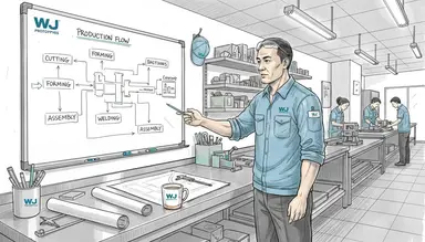
The sheet metal fabrication workflow for prototyping typically begins with digital design and DFM (Design for Manufacturability) analysis, followed by cutting, bending, welding, and surface finishing. China has become a preferred destination for this workflow due to its advanced fabrication facilities equipped with laser cutting machines, CNC press brakes, and automated welding systems. These capabilities allow Chinese manufacturers to produce highly accurate sheet metal prototypes with tight tolerances and consistent quality, even for complex geometries and low-volume orders.
In addition to technical strength, China’s integrated supply chains and fast production cycles significantly reduce lead times and costs for sheet metal prototyping. From material sourcing to finishing processes such as powder coating and anodizing, most services are available under one roof, minimizing delays between steps. This streamlined workflow enables global companies to iterate designs faster, validate form and function efficiently, and move smoothly from sheet metal prototypes to full-scale production.
Navigating the complexities of sheet metal fabrication requires precise design requirements, meticulous CAD modelling, and expert tooling setup to achieve high-quality prototypes. Common challenges include maintaining tight tolerances, selecting optimal materials like carbon steel or aluminium, and conducting thorough quality inspections to ensure assembly readiness. This article highlights critical pain points such as controlling bend radii, verifying dimensional accuracy, and applying appropriate finishing techniques to validate functional prototypes.
At WJ Prototypes, we understand these technical demands and deliver tailored sheet metal fabrication solutions to streamline your prototyping process. Our advanced manufacturing capabilities combined with rapid prototyping expertise allow you to optimise your designs while reducing lead times and controlling costs. Whether you need detailed dimensional inspection or precise forming operations, our ISO certified engineers are ready to support your project from concept to assembly. Explore how we can help you overcome fabrication challenges by visiting WJ Prototypes and learn about our comprehensive Rapid Prototyping Services. Take the next step to transform your sheet metal designs into reliable prototypes with expert guidance and world-class manufacturing technology.
Ready to reduce errors and accelerate product development? Contact WJ Prototypes now and turn your sheet metal fabrication workflow into a competitive advantage.
Defining design requirements starts with analysing your engineering needs, including dimensional tolerances and structural integrity. To optimise this process, evaluate potential fabrication techniques such as cutting or bending, ensuring your specifications align with standard capabilities.
When selecting materials, consider mechanical properties like tensile strength and corrosion resistance. Choose materials such as carbon steel for cost-effectiveness or stainless steel for corrosion resistance, balancing strength requirements and budget limits to optimise your prototype.
To prepare CAD models, use professional engineering software and maintain uniform material thickness. Ensure that you specify critical dimensions and tolerances clearly to facilitate accurate manufacturing and minimise errors during production.
Configuring machinery involves selecting appropriate tools and programming machines for specific cutting or bending operations. Verify parameters like machine tolerances and tool alignment to ensure accuracy and consistency during production runs.
To conduct effective quality inspections, utilise advanced measurement techniques such as coordinate measuring machines or laser scanners. Compare the manufactured parts against your CAD model, paying close attention to tolerance limits, to validate the precision and quality of your prototypes.
Apply surface treatments like deburring and anodising to enhance durability and aesthetics. Validate assembly readiness by checking compatibility and functional integrity of the parts, ensuring they meet the required performance standards for your prototype.
Sheet Metal Fabrication Guide for Precision Prototyping
Why Use Sheet Metal Fabrication - Complete Guide for Industry
Sheet Metal Fabrication 101 | Step-by-Step Guide for Precision Parts
Role of Sheet Metal Fabrication - Complete Guide
SERVICES
RESOURCES


