




- Room 1807, Unit 9, Building 2, Shangxing Commercial Street, Shangde Road, Shangxing Community, Xinqiao Subdistrict, Bao'an District, Shenzhen City, China
CONTACT US

WhatsApp



Contact Us
Our team is on stand by, waiting toassist you.

Videos
A large collection of educational videos and tutorials.

About Us
Learn about our company, leadership, and mission totransform manufacturing.

Privacy Policy
Applies to all personal information collected through and/or processed in connection.


Aerospace & UAV
WJ Prototypes is your 3D manufacturing partner from prototype to large scale production.

Consumer Electronics
New Product Introduction Solutions for Consumer Electronics.

Robotics & Automation
Need some assistance bringing your robotic device or parts from the sketch-board to reality?

Medical Devices
The medical industry needs high quality, dependable and safe parts and products.

Automotive
New Product Introduction Solutions for Automotive

Industrial Machinery
The main purpose of industrial prototyping is to take the product from drawings into the real world.


Sheet metal tolerances describe how much a part’s thickness, dimensions, and flatness can vary from the drawing and still be acceptable. Expect mill thickness tolerances of a few thousandths of an inch depending on gauge, laser-cut profile tolerances around ±0.1 mm on thin stock and looser on thick sections, and a common shop default of ±0.010 to ±0.020 inch for general linear features. The standards to check are ASME Y14.5 for geometric controls, ISO 2768 for general tolerance classes, and the relevant ASTM mill-product specs.
Sheet metal tolerances vary by material, process, and standard, with most dimensions controlled by explicit callouts while default tolerances cover non-functional features.
| Point | Details |
|---|---|
| Standards Guide Tolerances | ASME Y14.5, ISO 2768, and ASTM specifications define geometric, general, and mill tolerances for sheet metals. |
| Process Tolerance Impact | Laser cutting on thin sheet achieves tight tolerances near a tenth of a millimeter, loosening for thicker sections. |
| Control Key Dimensions | Focus on critical dimensions with explicit tolerances; default values suffice for non-functional features. |
| Importance of Drawing Details | Including material, flatness, and critical tolerances in drawings reduces costly rework and misunderstandings. |
| WJ Prototypes’ Approach | We prioritize function-critical tolerance information upfront for accurate quotes and efficient project flow. |
Three standards families cover almost everything you need to call out on a sheet metal drawing, and each one answers a different question.
ASME Y14.5 is the standard to reach for when a dimension controls fit or function rather than just appearance. It defines geometric dimensioning and tolerancing (GD&T), including limits of size, statistical tolerancing, and form controls, and it is the correct reference whenever you need profile or position callouts instead of a chain of linear dimensions. ISO 2768 fills a different role: it assigns general tolerance classes (f, m, c, v) to dimensions that carry no individual tolerance, so a drawing note can cover dozens of non-critical features in one line instead of dimensioning each one.
The ASTM specifications govern what comes off the mill before anyone cuts or bends it:
Knowing which spec applies tells you whether a thickness variation your supplier reports is within normal mill allowance or a genuine defect.
Mill tolerances vary by material, nominal thickness, and sheet width, so a single “sheet metal tolerance” number does not exist. A current gauge tolerance reference compiles ASTM-based thickness ranges by material and width band, which is the fastest way to check whether a reported variance is normal mill allowance.
| Material and spec | Nominal thickness range | Typical thickness tolerance |
|---|---|---|
| Carbon steel (ASTM A568/A1008) | 20 to 14 gauge | Tighter at thin gauges, wider at mid-range widths |
| Stainless steel (ASTM A480) | 20 to 12 gauge | Comparable band, tighter on narrower coil widths |
| Aluminum (ASTM B209) | 0.030 to 0.180 in | Tolerance widens with both thickness and sheet width |
For general linear and angular dimensions without individual callouts, ISO 2768 class “m” (medium) is a common shop default, and many fabrication shops independently default to roughly ±0.005 to ±0.020 inch on formed features depending on size, a range echoed in practical sheet metal design guidance.
Process tolerances ride on top of mill tolerances. Laser-cut profiles on thin material generally land tighter than on thick plate because heat distortion and kerf widen as the beam has to cut through more material. Punched holes tend to hold position better than the outer profile does, since the punch is a fixed tool registering against the sheet rather than a moving beam tracing an edge. Bend-to-feature distances depend on how consistently the press brake registers the part, so a feature near a bend needs a slightly looser tolerance than the same feature on a flat section unless the drawing calls out a tighter bend tolerance explicitly.
A plain linear dimension (length, width, hole diameter) controls size. Geometric tolerances control form, orientation, location, and runout, which is a different question entirely: a hole can be the right diameter and still sit in the wrong place, or a flange can be the right length and still tip off-angle.
For sheet metal specifically:
Hole-to-bend distances deserve particular attention because springback shifts the actual bend line slightly from the theoretical one, so a tight linear dimension from a hole to a bend is harder to hold than the same dimension between two holes on a flat face. ASME Y14.5 explains the symbology and material-condition modifiers (MMC, LMC) that let you express how much positional tolerance a hole gets as it approaches its size limits.
Pro Tip: Reserve GD&T callouts for the handful of features that actually control fit; dimensioning every hole with position tolerance just slows down quoting without improving the part.
Laser cutting and punching both hold tighter tolerances on thin material than on thick, and the gap between the two can be significant enough to change how you dimension a part.
Specify any hole that needs a true press fit as “ream to size” or “drill and ream” with a material condition callout, rather than trusting the as-cut dimension.
Flatness is measured in I-units, a metric that quantifies deviation relative to sheet length, and the condition the mill leaves the coil in has more effect on flatness than anything that happens afterward.
Standard cold-rolled sheet typically meets a flatness I-unit target below 40, with leveled and tension-leveled material achieving progressively lower I-unit values, indicating flatter sheet, according to ASTM-based gauge tolerance data. Lower I-units mean flatter material, and tension-leveled stock is the right call whenever a part has to sit flush against another surface without shimming.
Most dimensions on a sheet metal part do not need to be tight, and treating every dimension as critical is the single fastest way to inflate a quote.
Pro Tip: List your two or three functional dimensions first on the drawing with their tolerances, then apply a single general-tolerance note for everything else. It speeds up quoting and tells the fabricator exactly where to focus.
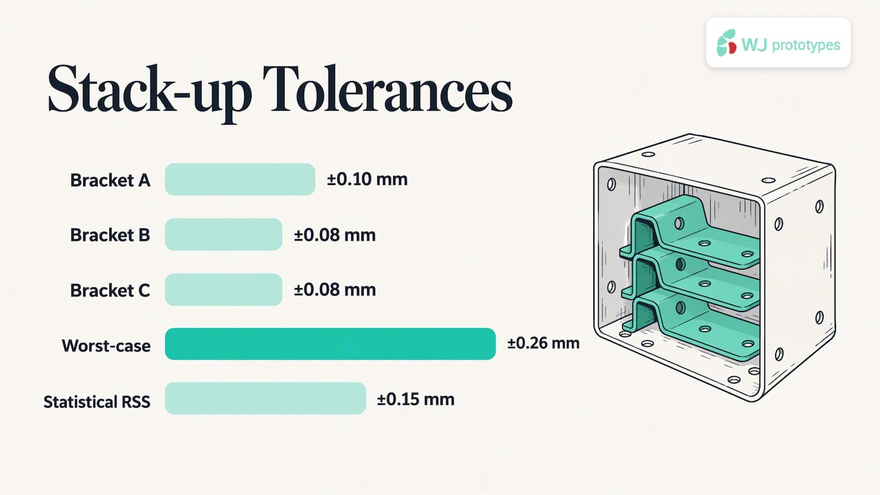
Worst-case stack-up adds every tolerance in a chain at its extreme, guaranteeing fit but often producing tolerances tighter than the process can hold economically. Statistical (RSS) stack-up assumes tolerances rarely all hit their limits simultaneously and allocates a looser budget per feature while still meeting a target yield.
Say three stamped brackets stack end to end inside a housing with a 0.060-inch nominal clearance:
| Method | Total tolerance | Resulting clearance range |
|---|---|---|
| Worst-case (sum of tolerances) | ±0.26 mm | ±0.26 mm |
| Statistical (root sum square) | ±0.15 mm | ±0.15 mm |
The worst-case total (0.10 + 0.08 + 0.08 = 0.26 mm) eats nearly a fifth of the clearance budget, while the RSS value (the square root of 0.10² + 0.08² + 0.08², about 0.15 mm) leaves more room. When a stack-up like this threatens to close a clearance to zero, tighten only the dimension with the largest individual tolerance rather than squeezing all three, since that is almost always the cheapest fix.
We run sheet metal fabrication as an ISO-certified operation, and the drawings that move fastest through our quoting process are the ones that state function-critical tolerances up front instead of leaving everything to a general note.
When you send an RFQ for a sheet metal part, include:
That level of detail lets us quote against your actual functional requirements rather than a generic assumption, which is usually where cost surprises come from later in the project.
The tolerances that cause the most trouble are rarely the tightest ones on the print. They are the ones nobody thought about, a hole-to-bend distance left at a default general tolerance when the part actually needs to seat against a mating bracket, or a flatness requirement implied but never stated. A fabricator can hold a tight callout if it is explicit; what a fabricator cannot do is guess which of your forty dimensions actually matters.
The fix is not tighter tolerancing everywhere. It is deciding, before the drawing leaves your desk, which two or three dimensions carry the functional requirement and sending those callouts to your fabricator early enough to discuss them before quoting, not after the first article fails inspection.
— Nas
We built our sheet metal fabrication service around the same principle this guide follows: function-critical tolerances get attention, everything else follows a sensible default, and there is no minimum order quantity holding up a prototype run while you wait to scale.
To get an accurate quote, send us your 3D model, a drawing with critical tolerances flagged, material and thickness, and any flatness or finish requirements. Our engineers review the file and flag anything that looks like it needs a tighter process (reaming, tension-leveled stock, secondary CNC work) before the quote goes out, not after the parts ship. If your part needs precision bores or press-fit holes beyond what laser cutting or punching alone can hold, we can pair the run with CNC machining for the finishing pass.
Start your sheet metal fabrication quote today and tell us which dimensions matter most.
A tolerance of roughly a tenth of a millimeter means a dimension can vary by plus or minus about 0.1 mm from its nominal value, a band tight enough to require precision cutting or secondary machining on most sheet metal features. Whether that tolerance is achievable depends on the process: laser-cut profiles on thin stock can approach this range, but thicker material typically cannot hold it without added finishing.
Sheet metal thickness is measured directly with a micrometer or caliper at multiple points, since mill tolerance allows some variation across a sheet. For a specified gauge, check the applicable ASTM table, A568/A1008 for carbon steel, A480 for stainless, or B209 for aluminum, to confirm the acceptable range for that nominal gauge and width.
A common shop default for general, non-functional sheet metal dimensions runs about ±0.010 to ±0.020 inch, with ISO 2768 class “m” (medium) frequently used as the drawing-note default for features without individual callouts. Functional features that control fit are usually held tighter and specified with explicit GD&T under ASME Y14.5 rather than a general tolerance.
Non-ferrous sheet metal, aluminum in particular, is most often specified by nominal thickness in inches or millimeters alongside the applicable ASTM B209 tolerance table rather than by a single universal gauge number. Gauge numbering systems differ between ferrous and non-ferrous materials, so citing the actual thickness and the governing spec avoids confusion between standards.
SERVICES
RESOURCES