



- Room 1807, Unit 9, Building 2, Shangxing Commercial Street, Shangde Road, Shangxing Community, Xinqiao Subdistrict, Bao'an District, Shenzhen City, China
CONTACT US

WhatsApp


Contact Us
Our team is on stand by, waiting toassist you.

Videos
A large collection of educational videos and tutorials.

About Us
Learn about our company, leadership, and mission totransform manufacturing.

Privacy Policy
Applies to all personal information collected through and/or processed in connection.
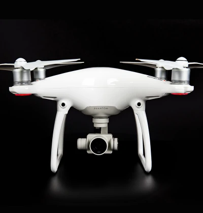

Aerospace & UAV
WJ Prototypes is your 3D manufacturing partner from prototype to large scale production.

Consumer Electronics
New Product Introduction Solutions for Consumer Electronics.

Robotics & Automation
Need some assistance bringing your robotic device or parts from the sketch-board to reality?

Medical Devices
The medical industry needs high quality, dependable and safe parts and products.

Automotive
New Product Introduction Solutions for Automotive

Industrial Machinery
The main purpose of industrial prototyping is to take the product from drawings into the real world.
TL;DR:
Tolerance in machining defines the permissible variation in a part's dimensions or geometry to ensure proper function and assembly. Properly specifying and understanding tolerances, especially using standards like GD&T and ISO 2768, reduces costs, prevents assembly issues, and improves product consistency. Accurate measurement and appropriate tolerance selection are critical for balancing quality and manufacturing efficiency.
Tolerance in machining is one of those concepts engineers reference constantly but rarely define with enough precision to prevent costly mistakes. What is tolerance in machining, exactly? It is the permissible range of variation in a part's dimensions or geometry that still allows the part to function as intended. Most people treat tolerances as simple numerical limits. They are far more than that. Tolerances define whether parts fit together, how assembly lines perform, and whether a product survives its operating environment. Getting tolerance right from the design stage saves money, reduces scrap, and separates functional parts from expensive failures.
| Point | Details |
|---|---|
| Tolerance defines acceptable variation | It specifies the permissible dimensional or geometric deviation that still allows a part to function correctly. |
| Standards like ASME Y14.5 and ISO 2768 govern tolerances | These standards create a shared language between designers, machinists, and inspectors across global supply chains. |
| Tighter is not always better | Tight tolerances increase cost, inspection time, and process complexity without always improving part performance. |
| Measurement tools must match tolerance demands | CMMs, micrometers, and calibrated gauges are selected based on the precision level required by the specification. |
| Datum selection directly impacts inspection | Poor datum choice causes parts to fail inspection even when they are physically within acceptable limits. |
The machining tolerance definition is straightforward on the surface. A tolerance specifies the total allowable variation between the upper and lower limits of a dimension. A shaft specified at 25.00 mm ±0.05 mm, for example, can measure anywhere from 24.95 mm to 25.05 mm and still be acceptable. That 0.10 mm window is the tolerance. What makes this concept technically deep is that tolerances apply to far more than linear dimensions. They govern angles, surface flatness, cylindricity, perpendicularity, and the positional relationship between features.
Two standards dominate how tolerance is communicated in professional manufacturing environments:
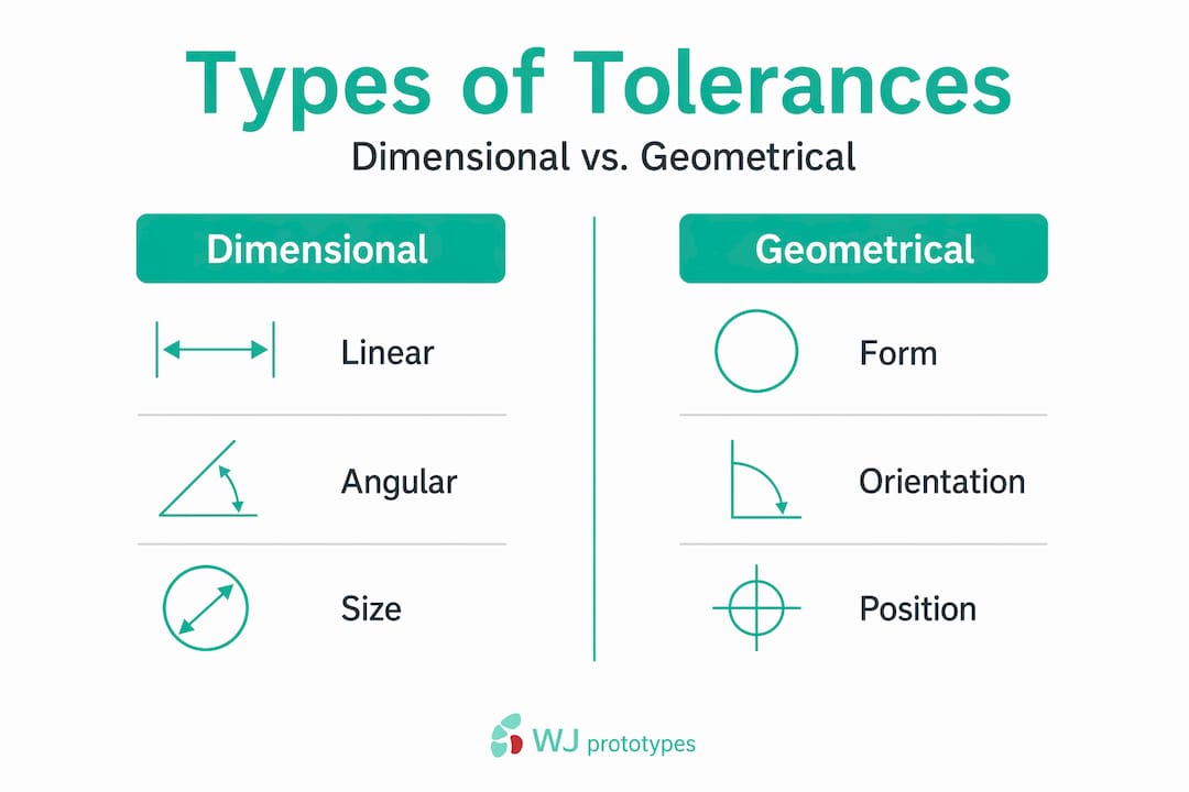
The distinction between dimensional and geometrical tolerances matters enormously in practice. Dimensional tolerances control size, such as a length, diameter, or angle between two surfaces. Geometrical tolerances control shape, orientation, and position, covering characteristics like flatness, parallelism, and true position. A part can pass every dimensional check and still fail assembly if its geometrical tolerances are not controlled. That is why GD&T defines functional control zones tied to measurement methods and datum references, not just size boundaries.
Understanding the types of machining tolerances is not an academic exercise. Each category addresses a specific failure mode in physical parts.
Dimensional tolerances cover linear and angular measurements. A slot width of 10.00 mm +0.00/−0.02 mm is a linear tolerance. A chamfer angle of 45° ±0.5° is an angular tolerance. These are the most common calls found on basic engineering drawings.
Geometrical tolerances go further and include five main categories:
Each type affects assembly and product performance differently. A shaft with excellent diameter tolerance but poor cylindricity can cause premature bearing wear. A bolt hole pattern with correct individual positions but poor group-level true position can prevent a mating flange from assembling. Interchangeability, the ability to swap one part for another without rework, depends on specifying the right tolerance type for every critical feature.
Here is where engineers make the most expensive decisions. Tight tolerances are not inherently better. They are appropriate when function demands them, and wasteful everywhere else.
 Standard machining tolerances sit between ±0.005" and ±0.002". Tight tolerances begin around ±0.001". Ultra-precision work pushes to ±0.0002" or tighter. Each step tighter changes the entire production workflow.
Consider what tightening a tolerance from ±0.005" to ±0.001" actually requires:
Industries like aerospace, medical devices, and precision robotics regularly work in the ±0.001" range because functional requirements demand it. A hip implant stem that fits improperly can cause implant loosening. A fuel control valve with excessive bore diameter variation will leak under pressure. For those applications, the cost premium is justified.
For a bracket mounting a non-critical cover panel, applying ±0.001" tolerances wastes money with zero functional benefit.
Pro Tip: Audit every tight tolerance on your drawing before releasing it to production. Ask yourself: what physically fails if this dimension is 0.003" wider? If the answer is nothing, loosen the tolerance. You will cut machining cost without losing part performance.
Knowing how to measure machining tolerance correctly is as important as specifying it correctly. A tolerance that cannot be reliably measured is functionally useless because you cannot confirm compliance.
Common measurement tools fall into a clear hierarchy based on required precision:
The choice of measurement method must match the tolerance being verified. Checking a ±0.0005" bore diameter with a standard caliper is not measurement, it is guessing. Beyond tool selection, datum setup during inspection is critical. Multiaxis machining errors can originate from axis and feed system behavior, not just the cutting process, which means inspection must account for how the part was fixtured and oriented during manufacture.
Pro Tip: Specify inspection datums on your drawing that match the functional assembly datums. When design datums and inspection datums differ, a part can measure in-tolerance on the CMM but still fail to assemble correctly on the production floor.
Most tolerance problems in manufacturing trace back to drawing errors, not machining errors. The specification is where quality is won or lost.
Relying too heavily on ISO 2768 defaults is the most common trap. ISO 2768 defaults can allow too much positional or orientation variation on features that are functionally critical. A pin that locates a mating assembly needs an explicit position tolerance, not a general note that falls under a medium class default. Designers who leave critical features under ISO 2768 without specific overrides are inviting silent assembly failures.
Ambiguous datum schemes cause another category of problems. If a datum is not physically reachable or measurable on the finished part, inspection will produce inconsistent results across different operators and machines. Effective datum selection directly determines whether parts pass inspection and assemble correctly in the field.
Other recurring pitfalls include:
The fix is not more tolerances. It is functional tolerancing, where every callout connects directly to a physical assembly or performance requirement. If you cannot explain why a specific tolerance is needed in terms of what breaks without it, the specification needs revision.
I have reviewed hundreds of drawings from clients across aerospace, medical, and industrial equipment sectors. The pattern is consistent. Engineers who deeply understand tolerance in CNC machining produce designs that machine cleanly on the first attempt. Engineers who treat tolerance as a formality paste a ±0.005" note in the title block and move on. Those designs generate RFIs, rework loops, and assembly failures that trace directly back to under-specified or inconsistently specified drawings.
What I have found is that the cost of tight tolerances is rarely the problem. The cost of the wrong tolerances, whether too tight in non-critical areas or too loose on functional surfaces, is where money disappears. I have seen components where 80% of the tight tolerances were on features with no assembly mating surface. The machinist spent three times longer on those features while the actual critical bore ran at a standard tolerance that barely kept the assembly together.
The practical fix is to treat your drawing as a communication document between design intent and the shop floor. Standards like ASME Y14.5 exist precisely because GD&T callouts tie tolerances to functional requirements and measurement methods, not just numerical limits. Engineers who invest in understanding GD&T and applying ISO 2768 correctly do not just improve individual parts. They reduce back-and-forth with suppliers, accelerate first-article approval, and build products that perform consistently across production runs. That is the real value of tolerance literacy.
— Nash
At WJ Prototypes, tolerance control is built into every step of the CNC machining workflow, from material selection through final inspection. If your design calls for precision CNC machining materials suited for tight tolerances, such as aluminum alloys, stainless steel, or engineering plastics, WJ Prototypes provides a material selection that covers the full range of prototype and production requirements. The CNC machining services include first-article inspection, CMM verification, and ISO-certified quality controls, ensuring parts meet your drawing specifications rather than approximations of them. Whether you are prototyping a single functional part or running a low-volume production batch, WJ Prototypes has the process controls and engineering support to translate your tolerance specifications into parts that perform.
Explore competitive CNC Machining Services with expert support from WJ Prototypes.
Whether you're comparing suppliers or looking to optimize costs, our team can help you evaluate the best option for your project.
👉 Request A Quote now or email us at info@wjprototypes.com to get started.
Standard CNC machining tolerances typically fall between ±0.005" and ±0.002" (±0.13 mm to ±0.05 mm) for general features. Tighter work begins at ±0.001", and ultra-precision applications reach ±0.0002" or better.
Tolerance defines the permissible variation in a single dimension. Fit describes the intentional clearance or interference between two mating parts, such as a shaft and bore, and is determined by the combination of tolerances assigned to each mating feature.
ISO 2768-mK specifies medium class linear and angular tolerances combined with K-class geometric tolerances for features that do not carry individual tolerance callouts on the drawing. Most CNC shops apply this as a default general tolerance.
GD&T uses geometric controls tied to datums and functional requirements, covering form, orientation, location, and runout beyond simple size limits. It defines how a feature must be shaped and positioned relative to other features, not just how large it is.
Tight tolerances require higher-precision equipment, better toolholding, more frequent inspection, and slower cutting conditions to control dimensional variation. Each factor adds direct time and cost to the machining process.
CNC Machining Materials | Ideal For Prototypes And Custom Parts
Complete Guide to the Role of CNC Machining - WJ Prototypes
Automotive Parts CNC Machining China
What Is Precision Machining and Why Accuracy Matters
Explore competitive CNC Machining Services with expert support from WJ Prototypes.
Whether you're comparing suppliers or looking to optimize costs, our team can help you evaluate the best option for your project.
👉 Request A Quote now or email us at info@wjprototypes.com to get started.
SERVICES
RESOURCES