



- Room 1807, Unit 9, Building 2, Shangxing Commercial Street, Shangde Road, Shangxing Community, Xinqiao Subdistrict, Bao'an District, Shenzhen City, China
CONTACT US

WhatsApp


Contact Us
Our team is on stand by, waiting toassist you.

Videos
A large collection of educational videos and tutorials.

About Us
Learn about our company, leadership, and mission totransform manufacturing.

Privacy Policy
Applies to all personal information collected through and/or processed in connection.


Aerospace & UAV
WJ Prototypes is your 3D manufacturing partner from prototype to large scale production.

Consumer Electronics
New Product Introduction Solutions for Consumer Electronics.

Robotics & Automation
Need some assistance bringing your robotic device or parts from the sketch-board to reality?

Medical Devices
The medical industry needs high quality, dependable and safe parts and products.

Automotive
New Product Introduction Solutions for Automotive

Industrial Machinery
The main purpose of industrial prototyping is to take the product from drawings into the real world.
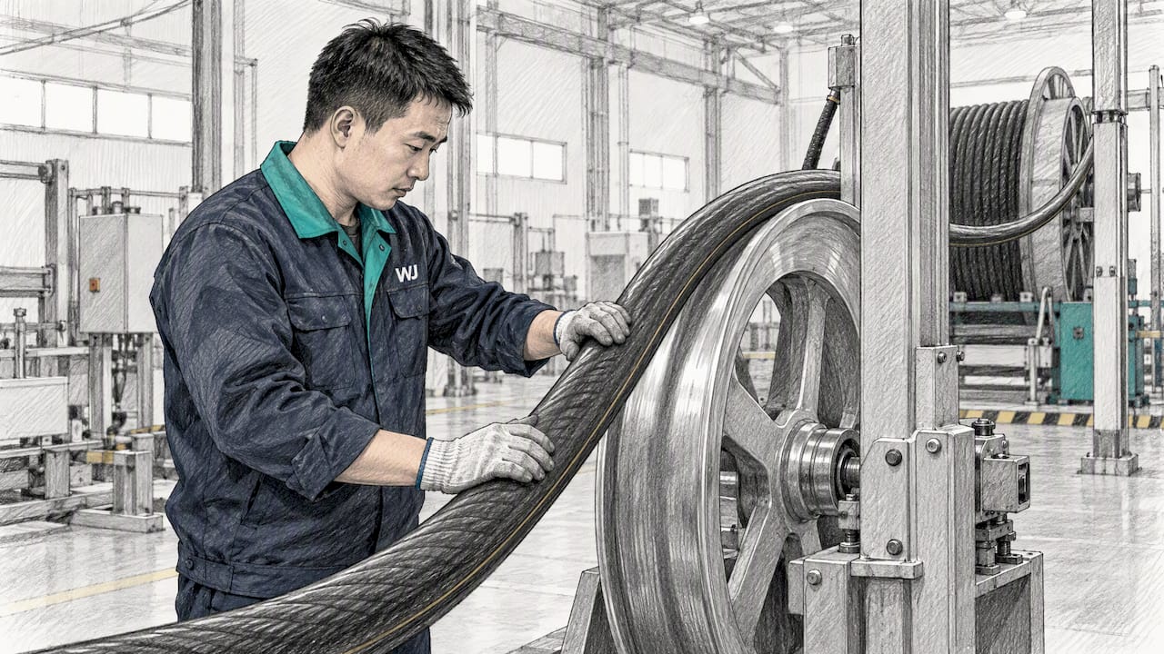
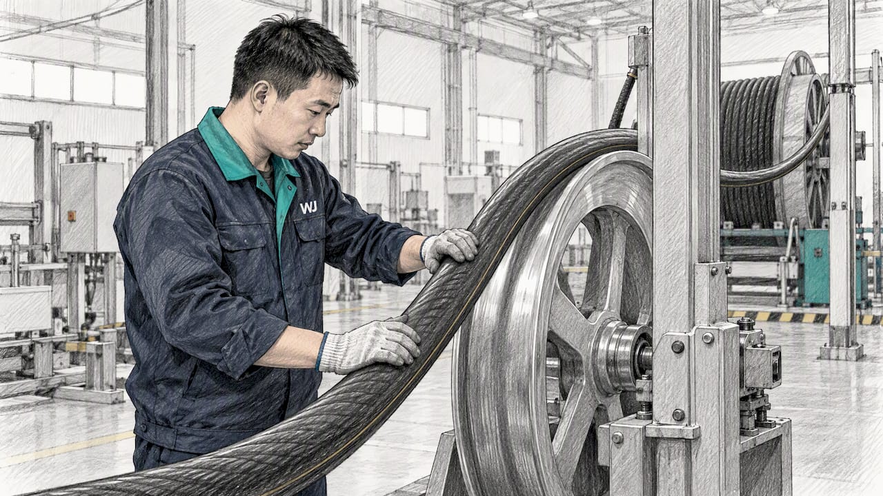
Minimum bend radius is the smallest inside curvature you can form into a cable, fiber, or sheet-metal part without cracking it, degrading its performance, or shortening its service life. For cables, use 20 times the outer diameter while pulling and 10 times the outer diameter once installed as starting multipliers, per FOA installation guidance. For sheet metal, compute the minimum inside radius as R = t × kR, and always confirm fixed exceptions on the manufacturer datasheet.
Understanding and adhering to minimum bend radius guidelines prevents material cracking, performance loss, and service life reduction in cables, fiber optics, and sheet metal parts.
| Point | Details |
|---|---|
| Proper calculation for cables | Use 20 times the outer diameter during pulling and 10 times after installation for safe bending. |
| Different specifications for bending | Manufacturers specify fixed radii or multipliers depending on whether the product is fiber, wire, or sheet metal. |
| Material-specific bending limits | Bending tighter than the minimum radius causes kinking, cracking, or increased signal loss, varying by material. |
| Precise pulley sizing | Pulley or capstan diameters should be twice the minimum bend radius to avoid damaging the cable during installation. |
| WJ Prototypes’ design support | We offer support on bend radius considerations for sheet metal and cable components during fabrication. |
Bend radius describes the distance from the center of curvature to the inside surface of the bend. Bend diameter is simply twice that value, and the two get confused often enough that a spec written as “radius” gets treated as “diameter,” producing a part or cable bent twice as tight as intended. Manufacturers choose between a fixed-radius spec and an OD-multiplier spec depending on the product: fiber cables and small-gauge wires often get a fixed millimeter value, while bulk cable and sheet stock get a multiplier tied to the physical dimension.
Bending tighter than the rated minimum shows up differently depending on the material:
One figure to anchor this: ITU-T G.657 sets a minimum design radius of 10 mm for category A1 fiber, a radius suited to tight routing, including inside a wall box.
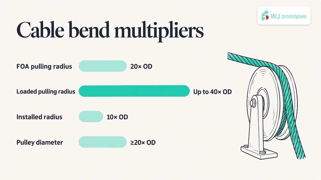
Cable has two different minimums depending on what stage of installation it is in. The minimum pulling bend radius applies while the cable is under tension, moving through conduit or over a sheave, and it needs to be larger because tension adds stress on top of the curvature. The minimum trained or installed bend radius applies once the cable is at rest in its final position, unstressed, and can be tighter.
Commonly cited multipliers vary slightly by source, which is why checking the datasheet matters more than memorizing one number:
Pulley and capstan sizing follows directly from the radius requirement: diameter equals twice the required radius, so a cable requiring a 10× OD minimum radius needs a pulley or capstan diameter of at least 20× OD. Mixing up radius and diameter at this step is a frequent and avoidable error, as FOA notes.
Before pulling cable, run through this checklist: align the capstan so the cable enters straight rather than at an angle, use sheaves sized to the pulling (not installed) radius, protect conduit exits with bushings to prevent edge contact, and store slack loops at or above the minimum installed diameter rather than coiling tightly to save space.
Pro Tip: When a spec sheet gives only one number without labeling it “radius” or “diameter,” treat it as a radius and verify with the manufacturer before cutting pulley stock.
Fiber-optic cable has some of the tightest, most standardized bend radius figures in the industry because signal loss is measurable and testable at small curvatures. ITU-T G.657 defines minimum design radii for bend-insensitive single-mode fiber across three common subcategories used in premises wiring and datacenter routing.
| G.657 subcategory | Minimum design radius | Typical use |
|---|---|---|
| A1 | 10 mm | General premises and access cabling |
| A2 | 7.5 mm | Tighter routing in access networks |
| B3 | 5 mm | Short-reach, in-building, datacenter routing |
Category B3’s 5 mm minimum reflects fiber engineered specifically for tight corners inside equipment racks and wall boxes, a use case that ITU-T’s companion documentation ties to short-reach, in-building applications. These numbers describe design radii under controlled macrobending loss testing, so pairing the fiber with compatible connectors and verifying system-level loss budgets still matters even when the cable itself tolerates the tight curve.
Sheet-metal minimum inside bend radius follows a straightforward formula: R(min) = t × kR, where t is material thickness and kR is a coefficient that depends on the alloy and temper. Mild steel typically uses a kR close to 1, stainless steel often runs higher due to its work-hardening behavior, and aluminum varies by alloy and temper, covered in more detail in the next section.
Bend allowance, the flat length consumed by the bend, uses the neutral-axis K-factor: BA = α × (π/180) × (R + K × t), where α is the bend angle in degrees and K is the K-factor describing where the neutral axis sits relative to the material’s inside surface. Grain direction affects the real-world minimum too: bending across the grain allows a tighter radius than bending parallel to it, so parts bent parallel to the rolling direction often need a larger radius to avoid cracking.
To work through a 90-degree bend on 2.0 mm stainless sheet with a kR of 1.5 and a K-factor of 0.33:
Pro Tip: Always confirm kR and K-factor values against the specific alloy and temper on order, since published handbook ranges shift between material suppliers and even between coil lots.
For a deeper look at calibrating K-factor against real production tolerances, our breakdown on K-factor calibration for sheet metal bending walks through the drift that shows up between theoretical and measured values.
Aluminum’s minimum bend radius shifts significantly with alloy and temper, since harder tempers crack sooner at tight radii than annealed or half-hard sheet. Common forming references group alloys roughly as follows:
As thickness increases, the minimum radius increases proportionally under the R = t × kR formula, and harder tempers push kR higher still. When a design calls for a radius tighter than the alloy’s minimum, annealing the material before bending or switching to a more formable temper is usually the practical fix rather than forcing the bend. For round or rectangular tubing, mandrel bending or roll bending equipment preserves wall thickness and roundness at radii that a simple press brake setup cannot achieve, and readers dealing with repeated cracking issues on press-braked parts may find value in reviewing material specification matching to stop press brake cracks.
Measuring an existing bend’s inside radius in the field is simple with a radius gauge set: match gauge leaves against the curve until one sits flush with no gap, then read the stamped value. If you only have a caliper, measure the diameter of the curve and divide by two, since mixing up radius and diameter at this step produces a reading twice or half the real value.
One number worth rechecking every time: the FOA’s 20×-OD pulling multiplier is a widely used starting point, but manufacturer datasheets occasionally specify a fixed radius for small-diameter or armored cable that overrides the multiplier entirely.
Tight-radius designs rarely fail in the CAD file. They fail on the shop floor when the specified radius does not match the tooling, material temper, or grain direction available. Looping in a fabricator before finalizing a drawing catches these mismatches while a design change is still cheap.
— Nas
Once the math is done, the harder part is finding a shop that will flag a radius problem before it becomes a cracked part or a failed pull test. Our sheet metal fabrication service can support your sheet metal part needs, and our CNC machining service covers features that a press brake cannot form at all. Submit your drawing through our online quote system for a quote.
The National Electrical Code sets bend radius requirements for specific conductor and raceway types rather than one universal multiplier, with the applicable minimum depending on cable construction and installation method. Always check the NEC table or the manufacturer’s listed minimum for the specific cable and raceway combination in your installation.
Minimum bend radius for wire depends on the insulation type, jacket construction, and whether multiple conductors are cabled together, so there is no single universal figure. Check the manufacturer’s datasheet for the specific cable assembly, since fixed-radius specs are common for smaller gauge wire.
For cable, multiply the outer diameter by the applicable factor: 20 times OD during pulling and 10 times OD once installed are common starting points per FOA guidance. For sheet metal, multiply material thickness by the alloy-specific kR coefficient using R = t × kR.
It refers to operating or installing a cable, fiber, or formed part at or above its rated minimum curvature so the material is not stressed beyond its safe limit. Staying within this limit during both installation and long-term use prevents cracking, kinking, and, in fiber, increased signal loss.
Yes, our sheet metal fabrication service can help with your sheet metal needs. Submit a drawing through our sheet metal fabrication page to get that review alongside a price.
SERVICES
RESOURCES