



- Room 1807, Unit 9, Building 2, Shangxing Commercial Street, Shangde Road, Shangxing Community, Xinqiao Subdistrict, Bao'an District, Shenzhen City, China
CONTACT US

WhatsApp


Contact Us
Our team is on stand by, waiting toassist you.

Videos
A large collection of educational videos and tutorials.

About Us
Learn about our company, leadership, and mission totransform manufacturing.

Privacy Policy
Applies to all personal information collected through and/or processed in connection.


Aerospace & UAV
WJ Prototypes is your 3D manufacturing partner from prototype to large scale production.

Consumer Electronics
New Product Introduction Solutions for Consumer Electronics.

Robotics & Automation
Need some assistance bringing your robotic device or parts from the sketch-board to reality?

Medical Devices
The medical industry needs high quality, dependable and safe parts and products.

Automotive
New Product Introduction Solutions for Automotive

Industrial Machinery
The main purpose of industrial prototyping is to take the product from drawings into the real world.
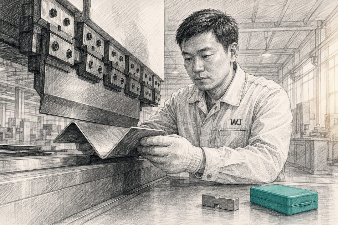
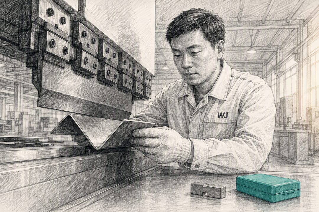
The most likely root cause of cracking is a mismatch between ASTM or EN material tolerances and the mill's actual delivered condition, which lets local bending strain exceed the metal's real ductility. Tolerance gaps in yield strength, trace elements, or grain orientation slip through unnoticed until the press brake finds them. Before ordering another run, pull the mill test report, check the bend radius against actual thickness, and confirm grain direction against the bend line.
TL;DR:
Material traceability and detailed test reports, including CEV and Charpy data, are essential to prevent cracks caused by spec mismatches from Chinese suppliers.
Heat-affected zones from cutting processes create hard, brittle edges that significantly increase the risk of crack initiation during bending.
Increasing bend radii, orienting parts perpendicular to the rolling direction, and performing trial bends can effectively identify borderline ductility issues early.
Strict segregation of heat lots and verifying actual material properties before production reduce batch-to-batch variability contributing to cracking.
Implementing a requalification process with small sample testing and controlled annealing can save costs and time by avoiding cracked parts in final assembly.
A sheet metal bend puts the outer surface into tension and the inner surface into compression. The tighter the radius relative to material thickness, the higher that outer-fiber tensile strain climbs, and once it exceeds the metal's elongation-to-failure, the surface splits. This is why the ratio of bend radius to thickness matters more than the nominal grade stamped on the certificate.
Nominal grade names are a poor proxy for forming behavior. Coils labeled the same grade can have different yield strengths, elongation percentages, and strain-hardening exponents, and those three numbers, not the grade name, decide whether a bend survives. Durmapress's analysis of bend cracking points to undersized radii, poor ductility, and wrong grain orientation as the three most common culprits, and all three show up repeatedly in cross-standard sourcing.
Grain direction adds another failure path. Rolled steel is stronger along the rolling direction and more brittle across it, so bending parallel to the grain concentrates strain into narrow bands and can trigger strain aging or Lüders bands, visible as fine longitudinal cracks along the bend apex.
On the shop floor, two crack signatures tell different stories:
Telling these apart before requalifying a batch saves real time.
ASTM and EN standards don't just use different naming conventions. They diverge in ways that change how a coil actually forms, and those differences rarely show up until the part is already cracking on the brake.
Before accepting a coil against a US or EU spec, the mill test report should carry the CEV calculation, the Charpy test temperature, an individual heat number for traceability, and a clear statement of delivery condition (normalized, as-rolled, or thermomechanically controlled). Runfei's guidance on cross-standard steel equivalence is blunt about this: equivalence charts are approximations, not guarantees, and blind cross-walking between grade families is where most surprises originate.
A spec mismatch on paper doesn't crack anything by itself. It's the combination with specific processing steps, common across Chinese fabrication shops, that turns a tolerance gap into a fracture on the press brake.
Cutting is the first risk point. Laser and plasma cutting both generate localized heat that hardens a narrow band along the cut edge, and that heat-affected zone has measurably lower ductility than the parent material just a few millimeters away. The Fabricator's analysis of edge cracking identifies this HAZ hardening, paired with undersized bend radii, as the leading documented cause of edge cracks in production.
A few other processing realities compound the problem:
Pro Tip: Cut a small edge-hardness check and a scrap trial bend from every new heat lot before it hits the production run. Both tests take minutes and catch HAZ hardening or aging problems that a paper MTR alone will never reveal.
Cracking is preventable, but only if the fix happens before the coil reaches the press brake, not after the first rejected part.
Pro Tip: If a trial bend produces even a hairline crack at the radius you'd normally use without issue, stop the run and requalify the material rather than pushing forward with a tighter process window. A hairline crack in testing is rarely a one-off.
Stop and requalify when edge hardness readings vary more than expected across a single coil, when a Charpy value is missing entirely from the MTR, or when a heat number on the physical coil tag doesn't match the paperwork. Any of those three should trigger destructive sample testing before that lot touches a production part, particularly for ISO 2768 tolerance-sensitive applications where a cracked part means a failed inspection, not just cosmetic scrap.

Run this before the coil ever reaches the brake:
Some manufacturers run sheet metal fabrication under ISO-certified process controls that address common gaps. Incoming coil gets checked against its mill test report before production release, with heat-lot traceability maintained through the run.
The working sequence looks like this:
Engineers can review permitted alloys and grades on the sheet metal materials page before submitting a specification.
Spending an extra day verifying an MTR feels wasteful right up until a production run cracks on the brake and costs a week. Reserve strict controls, full CEV and Charpy verification, trial bends, heat-lot segregation, for parts where failure means a safety or performance problem, and accept looser sourcing only on genuinely non-critical brackets and covers. The real fix isn't a smarter bend radius calculation. It's treating material specification checks as an engineering gate inside procurement, not a paperwork step that happens after the order already shipped.
— Nas
Some manufacturers run controls like full MTR review against specified ASTM, EN, or GB standards, heat-lot traceability, trial bending before production commitment, and annealing when trial results indicate. This provides a documented pre-bend qualification step, helping avoid discovering ductility problems after parts have cracked and schedules have slipped.
If you're sourcing sheet metal parts and want that qualification step handled before your specification meets a Chinese press brake, submit your drawings and MTR requirements through the sheet metal fabrication quote page and request a trial bend as part of your order.
The most frequent mistakes are using too tight a bend radius for the material thickness, bending parallel to the grain direction instead of across it, and trusting a nominal grade name instead of verifying actual yield strength and elongation on the mill test report.
The general rule is that the inner bend radius should be at least equal to the material thickness for ductile low-carbon steel, with larger radii for higher-strength or unverified material, and the bend line should run perpendicular to the rolling direction whenever possible.
Flanging is a bending operation that forms a narrow, raised edge at a right angle along the perimeter of a flat part to add stiffness or create a mounting surface, and it carries the same radius and grain-direction cracking risks as any other bend.
The most common defects are edge cracking from heat-affected zones after cutting, surface cracking at the bend apex from insufficient ductility, and dimensional inconsistency from batch-to-batch material variation, all of which trial bending and MTR verification catch before full production.
Request a mill test report with an individual heat number, explicit CEV calculation, Charpy impact test temperature, and stated delivery condition, then run a small trial bend, a step suppliers like WJ Prototypes build into standard order processing.
Sheet Metal Fabrication Workflow for Prototyping in China
Sheet Metal Fabrication in China - Trends and Innovations
The Real Cost of Undercuts in China Tooling Budgets
Machining PEEK: A Precision Guide for Engineers
SERVICES
RESOURCES