



- Room 1807, Unit 9, Building 2, Shangxing Commercial Street, Shangde Road, Shangxing Community, Xinqiao Subdistrict, Bao'an District, Shenzhen City, China
CONTACT US

WhatsApp


Contact Us
Our team is on stand by, waiting toassist you.

Videos
A large collection of educational videos and tutorials.

About Us
Learn about our company, leadership, and mission totransform manufacturing.

Privacy Policy
Applies to all personal information collected through and/or processed in connection.
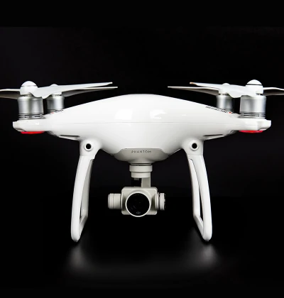

Aerospace & UAV
WJ Prototypes is your 3D manufacturing partner from prototype to large scale production.

Consumer Electronics
New Product Introduction Solutions for Consumer Electronics.

Robotics & Automation
Need some assistance bringing your robotic device or parts from the sketch-board to reality?

Medical Devices
The medical industry needs high quality, dependable and safe parts and products.

Automotive
New Product Introduction Solutions for Automotive

Industrial Machinery
The main purpose of industrial prototyping is to take the product from drawings into the real world.
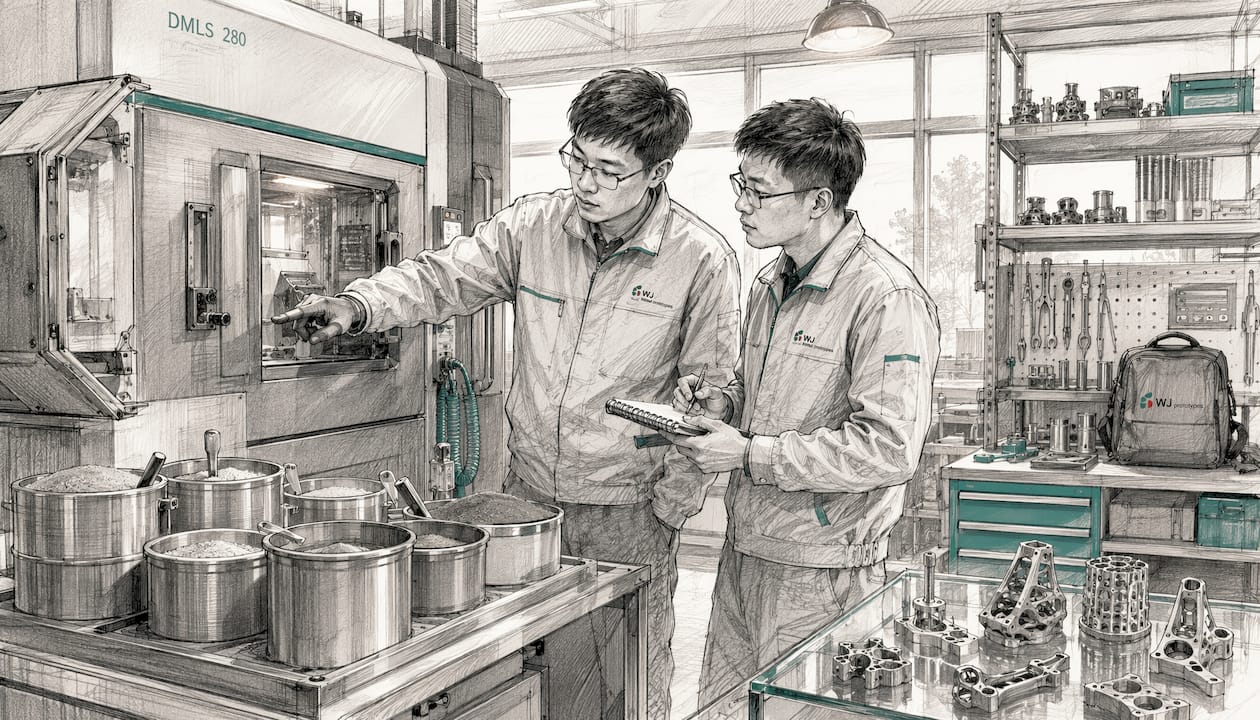

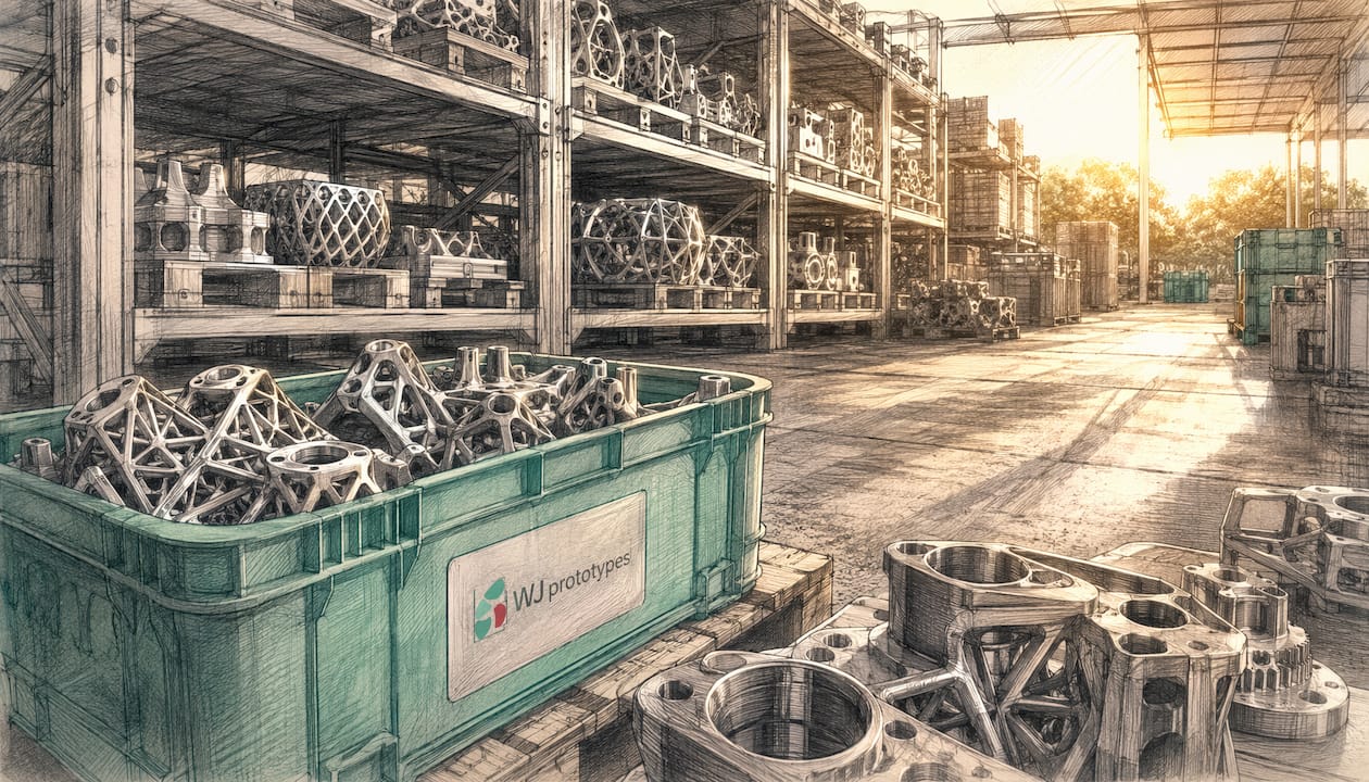
DMLS and SLM are the same core technology. Both are laser powder bed fusion (LPBF) processes that fully melt metal powder layer by layer to produce near-full density parts with relative densities above 99%. The distinction is mostly branding and historical naming, not a fundamental process difference.
That said, practical usage has drifted in a consistent direction. DMLS (Direct Metal Laser Sintering) is the term EOS GmbH trademarked and popularized, and it tends to appear in contexts involving complex alloys: stainless steels, cobalt-chrome, nickel superalloys. SLM (Selective Laser Melting) is the term more commonly applied to pure or near-pure metals like titanium and aluminum, where uniform melting behavior is easier to achieve. Neither term accurately describes what modern machines actually do, since both fully melt the powder rather than sinter it.
The real variables are machine configuration: laser count, power output, scan strategy, and parameter sets. Those factors drive differences in speed, surface finish, and material compatibility far more than the acronym on the machine.

| Dimension | DMLS | SLM |
|---|---|---|
| Process type | Laser powder bed fusion | Laser powder bed fusion |
| Melting approach | Full melting (historically “sintering”) | Full melting of powder |
| Typical materials | Alloys: stainless steel, CoCr, Ni superalloys, Ti alloys | Pure/near-pure metals: Ti, Al, steel |
| Part density | >99% relative density | >99% relative density |
| Naming origin | EOS GmbH trademark | Generic industry term |
| ISO/certification | Yes, widely certified | Yes, widely certified |

Industry standards, including those referenced in peer-reviewed LPBF research, treat DMLS and SLM as equivalent process categories. The ISO/ASTM 52900 additive manufacturing terminology standard groups both under powder bed fusion.
DMLS was coined by EOS GmbH in the 1990s. The word “sintering” in the name is a legacy artifact: early systems partially sintered metal powders rather than fully melting them. Modern DMLS machines fully melt the powder, producing fully dense parts. The name stuck because EOS built a dominant market position, and the term became shorthand for industrial metal LPBF across aerospace, medical, and tooling sectors.
The process works like this: a recoater blade spreads a thin layer of metal powder (typically 20–60 µm thick) across a build platform. A high-power fiber laser then scans the layer according to the part’s cross-section, fully melting the powder. The platform drops by one layer thickness, a new powder layer is spread, and the cycle repeats until the part is complete. The entire process runs inside a sealed chamber flooded with argon or nitrogen to prevent oxidation of reactive metal powders.
SLM was developed independently by researchers at the Fraunhofer Institute in the late 1990s, with the explicit goal of achieving full powder melting rather than partial sintering. The term “selective laser melting” is technically more accurate than DMLS for what both processes do today. SLM Solutions Group commercialized the term, though it has since become a generic descriptor used across the industry.
In practice, SLM systems often run at higher laser power and are configured for pure or near-pure metals where the melting point is uniform across the powder. Alloys with wide melting ranges can behave unpredictably under the high-energy conditions typical of SLM configurations.
| Factor | DMLS | SLM |
|---|---|---|
| Process type | Laser powder bed fusion | Laser powder bed fusion |
| Melting approach | Full melting (alloy-optimized) | Full melting (pure-metal-optimized) |
| Typical materials | Stainless steel, CoCr, Inconel, Ti alloys, maraging steel | Pure Ti, pure Al, stainless steel |
| Part density | >99% | >99% |
| Tolerances | ±0.1–0.2 mm depending on geometry | ±0.1–0.2 mm depending on geometry |
| Build speed | Moderate (single-laser typical) | Fast (multi-laser configurations available) |
| Surface finish (as-built) | Ra 6–15 µm | Ra 6–15 µm |
| Post-processing | Stress relief, support removal, machining | Stress relief, support removal, machining |
| Typical applications | Aerospace tooling, medical implants, industrial parts | Aerospace structures, biomedical, automotive |
| Cost drivers | Machine time, powder, post-processing | Higher machine cost, argon, post-processing |
| Certification maturity | High (EOS ecosystem, AS9100, ISO 13485) | High (SLM Solutions ecosystem) |
Both technologies produce parts with near-identical mechanical performance when parameters are optimized for the specific material. The table above reflects typical configurations, not absolute limits. A well-tuned DMLS system can match SLM build speeds with upgraded laser hardware, and SLM systems can process many alloys with careful parameter development.
The differences between DMLS and SLM are real but narrow. The shared foundation is more significant than the distinctions.
When engineers ask whether to use DMLS or SLM, the honest answer is often: ask the machine shop which term they use for the material you need, then evaluate their parameter sets and certification documentation.
The acronym matters less than the machine, the material, and the vendor’s parameter library. Here is how to think through the decision.
Pro Tip: When evaluating vendors, ask for their specific parameter set documentation for your target material, not just a list of materials they “support.” A vendor who can show you their validated process parameters, density test results, and post-processing protocol for Inconel 718 or Ti-6Al-4V is worth far more than one who lists the material on a spec sheet. The acronym on the machine is irrelevant; the parameter library is everything.
Wjprototypes holds ISO certification and brings direct engineering experience across aerospace, medical, and automotive DMLS applications. Their team can advise on DMLS design and performance trade-offs for your specific geometry and material before you commit to a build.
When your project calls for high-density metal parts with tight tolerances and no room for process ambiguity, Wjprototypes is a direct path from CAD to certified part. As an ISO-certified manufacturer with hands-on experience in DMLS across aerospace, medical, and industrial applications, Wjprototypes gives engineering teams the parameter validation and material expertise that generic print services cannot match.

The practical advantage is straightforward: you get a manufacturing partner who has already qualified the process for the alloys you are likely using, from Inconel and CoCr to Ti-6Al-4V and 17-4 PH stainless. No test-build guesswork, no undocumented parameter sets. Wjprototypes also offers CNC machining, sheet metal fabrication, and injection molding under one roof, so post-processing and hybrid workflows stay in a single supply chain.
Get an instant quote for your metal AM project at Wjprototypes rapid prototyping services and have a qualified engineer review your geometry and material requirements before the first layer is laid down.
Yes, in practice. Both are laser powder bed fusion processes that fully melt metal powder to produce parts with greater than 99% relative density. The naming difference is largely historical and branding-driven, not a fundamental technical distinction.
SLM is typically configured for pure or near-pure metals with uniform melting points, while DMLS is more commonly used with complex alloys that have varying melting ranges. Modern machines in both categories fully melt the powder; the difference lies in parameter optimization and historical naming conventions.
Neither is categorically better. Multi-laser SLM systems offer faster build rates, but DMLS systems have broader alloy compatibility and more mature certification documentation in many industrial sectors. The right choice depends on your material, volume, and certification requirements.
DMLS achieves tolerances of ±0.1–0.2 mm depending on part geometry and material, with small features achievable down to approximately 0.15 mm. Tighter tolerances typically require CNC finishing after the build.
Wjprototypes offers DMLS services with validated parameters across a range of industrial alloys, supported by ISO certification and engineering expertise in aerospace, medical, and automotive applications. Contact their team for material-specific guidance and an instant project quote.
DMLS and SLM are the same laser powder bed fusion process under different names, with practical differences driven by alloy compatibility and machine configuration rather than any fundamental process distinction.
| Point | Details |
|---|---|
| Process equivalence | Both DMLS and SLM fully melt metal powder to achieve >99% relative density parts. |
| Key practical difference | DMLS suits complex alloys; SLM is optimized for pure metals with uniform melting points. |
| Speed gap | Multi-laser SLM systems achieve build rates up to 5x faster than single-laser DMLS systems. |
| Tolerance capability | Both processes achieve ±0.1–0.2 mm as-built; CNC finishing is needed for tighter specs. |
| Wjprototypes | ISO-certified DMLS manufacturer with validated alloy parameters for aerospace, medical, and industrial projects. |
SERVICES
RESOURCES