




- Room 1807, Unit 9, Building 2, Shangxing Commercial Street, Shangde Road, Shangxing Community, Xinqiao Subdistrict, Bao'an District, Shenzhen City, China
CONTACT US

WhatsApp


Contact Us
Our team is on stand by, waiting toassist you.

Videos
A large collection of educational videos and tutorials.

About Us
Learn about our company, leadership, and mission totransform manufacturing.

Privacy Policy
Applies to all personal information collected through and/or processed in connection.


Aerospace & UAV
WJ Prototypes is your 3D manufacturing partner from prototype to large scale production.

Consumer Electronics
New Product Introduction Solutions for Consumer Electronics.

Robotics & Automation
Need some assistance bringing your robotic device or parts from the sketch-board to reality?

Medical Devices
The medical industry needs high quality, dependable and safe parts and products.

Automotive
New Product Introduction Solutions for Automotive

Industrial Machinery
The main purpose of industrial prototyping is to take the product from drawings into the real world.
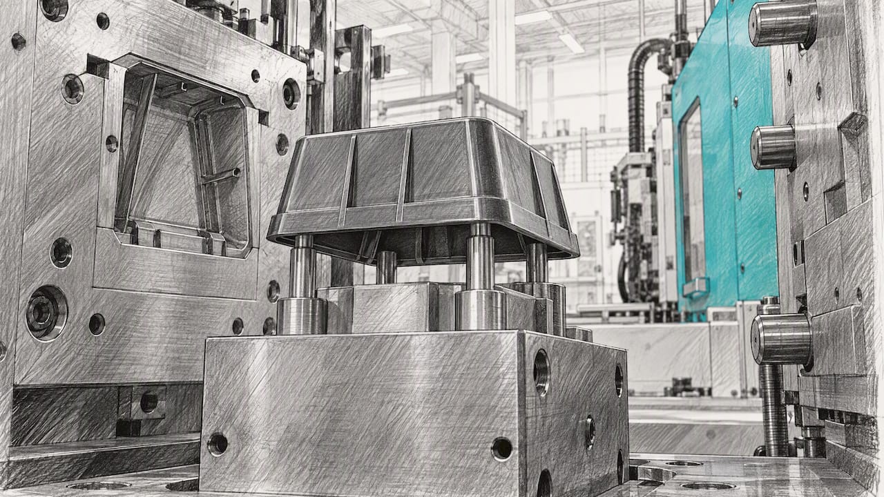
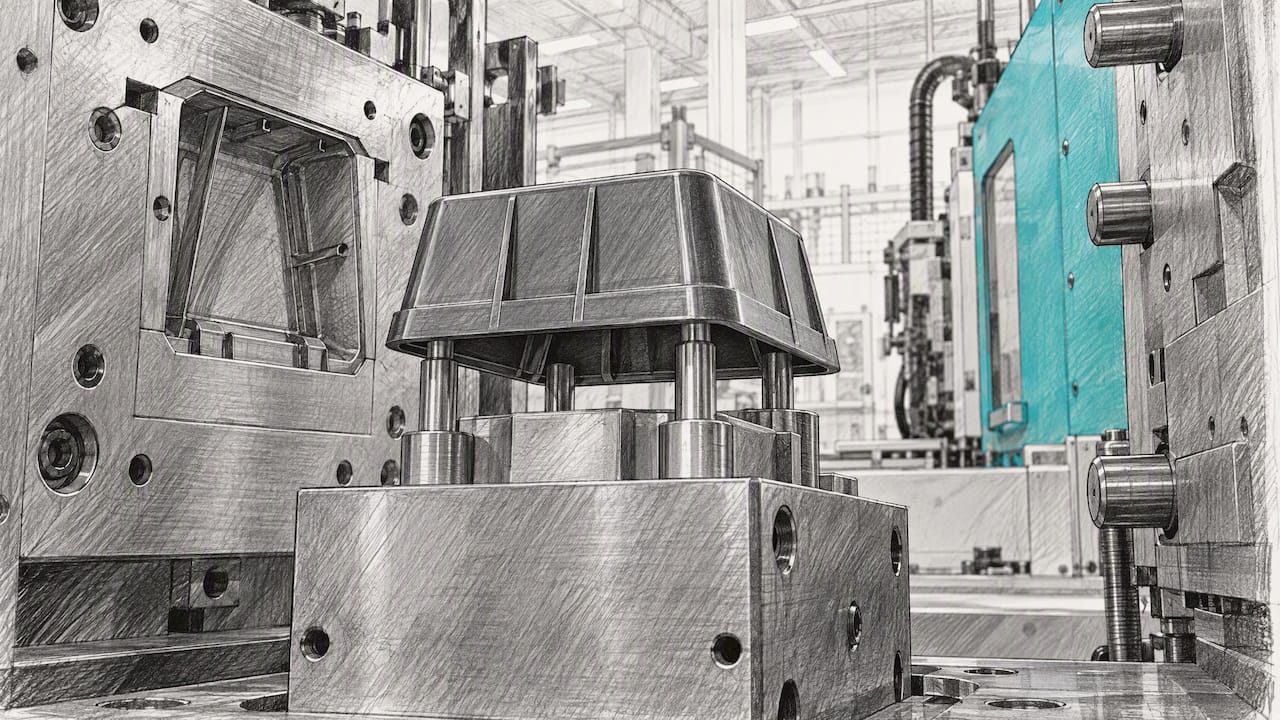
Use roughly 1°–2° of draft on most vertical faces, about 0.5° on shallow ribs, and 3° or more on shutoffs and metal-on-metal sliding surfaces. Then add draft as features get deeper, as texture gets heavier, and as your resin shrinks more. The sections below give the depth formula, the texture adjustments, and the CAD steps to apply them.
Draft angles in plastic parts are based on feature depth, surface texture, material shrinkage, and whether faces are on the core or cavity side.
| Point | Details |
|---|---|
| Use initial draft range | Start with 0.5° to 2° for most vertical walls, increasing for deeper or textured features. |
| Calculate draft from depth | Estimate about 1° of draft per inch of mold depth, then adjust for texture and material properties. |
| Account for surface texture | Add 0.5° to 1° for fine matte textures and more for heavy textures to prevent drag and scuffing. |
| Adjust draft for ribs and bosses | Increase draft as ribs and bosses become taller or deeper to avoid tearing or sticking. |
| Validate draft early with CAD and prototypes | Apply draft features in CAD, analyze, and verify with prototypes to ensure ease of ejection and surface quality. |
A good starting point for most plastic parts is the commonly cited 0.5°–2.0° range, which assumes uniform wall thickness and radii instead of sharp corners. Draft exists to ease ejection, so every vertical face parallel to the mold’s line of draw needs some taper, on both the core and the cavity side.
Use these baselines as your working numbers:
Pick the low end when tolerances are tight, the surface is polished and the feature is shallow. Pick the high end for deep pockets, textured faces and anything you cannot afford to scuff.
A few quick pairings help. A shallow boss under half an inch tall can live at 0.5°–1°. A wall about an inch deep is comfortable at 1°–2°. A feature three inches deep should start at 3° before you adjust for anything else.
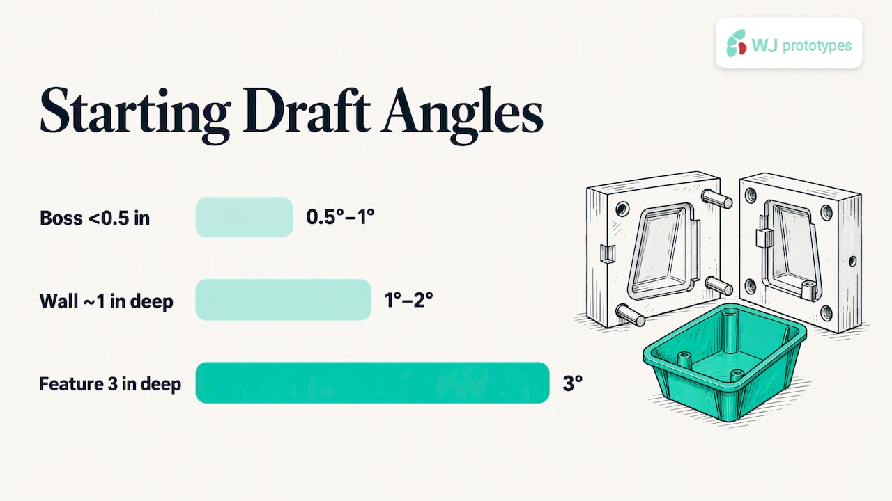
Pro Tip: Put a general note on the drawing (“draft on all faces parallel to the line of draw unless noted”) and call out exceptions feature by feature, so the toolmaker never has to guess.
The standard shortcut is about 1° of draft for every inch of mold depth. Treat it as a baseline, then adjust.
Take a worked example. Say a boss stands 2.5 inches tall. The baseline is 2.5°. If the face carries a fine matte texture, you might add another 1°, which lands near 3.5°, and then round to 3.5° or 4° on the drawing. That number is an illustration of the method, not a universal spec.
The formula underestimates in a few cases: shutoffs, metal-on-metal sliding surfaces and heavy texture. In those cases, the same source notes that more draft is needed, so start higher and ask the molder to tighten later if function allows. Where a part is expensive to re-cut, carry a safety margin on the tooling drawing. Removing steel later is easier than adding it.
Texture raises the friction between the part and the steel, and the microscopic peaks of a textured surface drag against the mold as the part slides out. The result is drag marks, scuffing and sometimes stuck parts. Engineering references note that textured parts need more draft, and the rule of thumb is to add allowance as texture gets deeper.
Planning considerations:
Where you can, orient texture so its grain runs with the direction of release, and specify the shallowest texture that still delivers the look you want. Deeper texture costs you draft, which costs you crisp, parallel-looking walls.
Pro Tip: Run your intended texture on a prototype or a sample plaque before final tooling. A texture that looks great at 1° can drag at the same angle once real resin and a real ejection stroke are involved.
Ribs commonly start at about 0.5° per side, but depth, fillet shape and wall thickness can push that higher. Small or deep ribs are one of the places where the standard rule runs short, because the part grips the tool along a narrow, tall slot.
Watch for these failure modes:
As a planning heuristic, keep a rib noticeably thinner than the wall it attaches to and increase its draft as it gets taller, using the 1° per inch depth rule as a floor. A short rib at 0.5° is fine; a rib an inch or more tall deserves more.
Plastics shrink as they cool, and the part tends to grip the core as it contracts. That is why greater plastic shrinkage calls for greater draft, and why textbook ranges run wider than a single number. The Texas A&M mold design notes also tell designers to plan around shrinkage allowance and mold polishing alongside draft.
Practical guidance:
Whether a face sits on the core or the cavity decides where the part wants to stay when the mold opens. The part generally shrinks onto the core, so core-side faces often need generous draft to release cleanly, while cavity-side faces must also be drafted so the part leaves the cavity. The Texas A&M notes state plainly that draft is needed in both core and cavity for easy ejection.
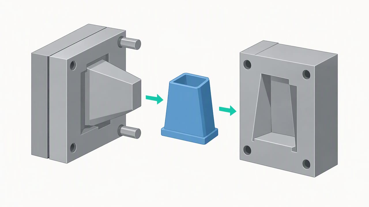
Shutoffs, where steel slides against steel to form a through-hole or window, are the exception to the gentle ranges above. Metal-on-metal sliding surfaces need more draft than ordinary faces, and 3° or more is a sensible planning value. Too little angle there wears the steel and flashes the part.
Ejection hardware also interacts with draft. Ejector pins push at chosen points, and stripper plates push around a perimeter, but neither can compensate for a face that grips the tool.
Put these notes on the tooling drawing:
Pro Tip: Mark the cosmetic side on the drawing and ask where the ejector pins will land before you finalize the draft scheme. A tiny pin mark and a tiny draft change often trade off against each other.
Build draft into the model before anyone talks about tooling. A simple workflow:
Keep the limits of prototyping in mind. Printed parts verify geometry and fit, but they do not reproduce production shrinkage or surface friction. For deeper process steps, see our guides on the injection molding workflow and on getting accurate prototypes fast, and our post on VDI and Mold-Tech draft rules if textured tooling is in play.
Most draft arguments come down to a designer wanting walls that look straight and a molder needing parts that leave the tool without drama. When a part has a function that depends on parallel faces, negotiate a specific tolerance on those faces. Everywhere else, take the extra half degree. A scuffed, sticking or broken part costs far more than a slightly tapered wall ever will.
My own checklist runs in a fixed order: define the draw, pick the material, set draft by depth and texture, run the DFM check, then prototype whatever feature worries you most. These choices inform our approach to customer parts.
— Nas
Our team works with product designers and engineering groups who want a second set of eyes on a draft scheme before steel is cut. We offer injection molding and rapid prototyping from our ISO-certified operation, with experienced engineers reviewing your model alongside you.
Send us your CAD and we will come back with specific draft recommendations. Request a quote or DFM review for your injection-molded part and tell us the material, texture and depth of your trickiest features.
There is no single legal minimum; common practice starts around 0.5° per side for ribs and shallow features. Many parts use 0.5°–2.0° overall, and deeper or textured faces need more.
Start with the depth rule: about 1° per inch of mold depth. Then add allowance for texture, high-shrink materials and shutoffs, and confirm the final value with your molder.
Draft angle is the small taper on faces parallel to the mold’s line of draw. It lets the part slide out of the mold without dragging, scuffing or sticking.
Yes. Texture increases friction during ejection, so fine matte faces typically need a bit more angle and heavy texture needs several degrees more. Confirm the exact value with your molder or texture supplier.
SERVICES
RESOURCES