




- Room 1807, Unit 9, Building 2, Shangxing Commercial Street, Shangde Road, Shangxing Community, Xinqiao Subdistrict, Bao'an District, Shenzhen City, China
CONTACT US

WhatsApp



Contact Us
Our team is on stand by, waiting toassist you.

Videos
A large collection of educational videos and tutorials.

About Us
Learn about our company, leadership, and mission totransform manufacturing.

Privacy Policy
Applies to all personal information collected through and/or processed in connection.


Aerospace & UAV
WJ Prototypes is your 3D manufacturing partner from prototype to large scale production.

Consumer Electronics
New Product Introduction Solutions for Consumer Electronics.

Robotics & Automation
Need some assistance bringing your robotic device or parts from the sketch-board to reality?

Medical Devices
The medical industry needs high quality, dependable and safe parts and products.

Automotive
New Product Introduction Solutions for Automotive

Industrial Machinery
The main purpose of industrial prototyping is to take the product from drawings into the real world.


Mold‑Tech's technical guidance calls for roughly 1° of draft per 0.0005"–0.0006" (about 12.5–15 µm) of texture depth, with a commonly cited alternate rule of 1.5–2° per 0.001" for deeper finishes. VDI 3400 grades map loosely to similar bands, but neither standard replaces trial shots. Increase draft for shrink‑toward features, lifters, and high‑shrink resins, and always confirm the final number with a sample tool run before cutting steel.
TL;DR:
- Increasing draft angles is necessary for deeper textures, with a baseline of about 1° per 0.0005"–0.0006" of texture depth; more conservative rules suggest 1.5°–2° per 0.001".
- The selection of draft depends on the texture grade, resin type, and part features, requiring cross-checking between VDI, Mold-Tech, and SPI standards to avoid mismatches.
- Texture application methods like EDM and chemical engraving can cause inconsistencies, so profilometer readings and physical texture samples are essential for quality control.
- Resin choice and feature geometry significantly influence draft requirements, with semi-crystalline resins and thin or complex features demanding higher draft angles than standard guidelines.
- Clear communication and verification protocols, including signed trial shots and texture cards, are crucial to prevent costly rework or re-tooling due to misunderstandings between design specifications and manufacturing standards.
Texture and draft are not two separate specifications you pick independently. They are one decision. Every micron of texture depth you add to a cavity wall increases the mechanical grip between the plastic part and the steel, and that grip has to be overcome by draft during ejection or the part scuffs, whitens, or simply refuses to release.
This is where Mold‑Tech guidelines and VDI 3400 standards in China do the real work of dictating draft angle specifications. Chinese toolmakers work across both systems daily, often on the same job, because Western OEM drawings specify VDI grades, while many Asian resin suppliers and moldmakers default to Mold‑Tech texture cards. If your drawing calls out a VDI grade but your supplier quotes Mold‑Tech numbers, you need a way to translate between them, and you need that translation to be conservative, not optimistic.
The practical upshot for anyone doing China mold manufacturing: draft angle considerations are not a fixed number you copy from a textbook. They are a function of texture depth, resin shrinkage, and how a given feature gets ejected. Get the mapping wrong and you pay for it in scrap, rework, or a mold that has to go back for hand‑stoning after the first trial run.
VDI 3400 is a German surface finish reference standard that defines numbered grades, roughly VDI 0 through VDI 45, each corresponding to an approximate roughness (RA) range. Lower numbers describe near‑glossy finishes; higher numbers describe deep, coarse textures used for grained plastics, rubberized housings, or leather‑look automotive trim. VDI grades are a roughness classification, not a texture pattern, so two VDI‑36 textures from different suppliers can still look different even though they measure the same on a profilometer.
Mold‑Tech is a commercial texture brand with its own catalog of named patterns (leather grains, matte stipples, geometric finishes) and its own published depth‑to‑draft guidance. Where VDI gives you a roughness number, Mold‑Tech gives you an actual texture family plus a data sheet telling you how much draft that specific pattern needs. That difference matters in practice:
All three coexist because supply chains are global and nobody has fully standardized on one system. A drawing that only lists an SPI finish, with no VDI or Mold‑Tech cross‑reference, is a common source of confusion when the tooling gets quoted through a Chinese shop that thinks in VDI grades. Specify both where you can.
The core number every mold designer should memorize comes straight from Mold‑Tech's own technical sheet: expect to add roughly 1° of draft for every 0.0005"–0.0006" (12.5–15 µm) of texture depth. That is the baseline rule for standard grain and stipple finishes on vertical or near‑vertical walls with a straightforward, shrink‑away ejection path.
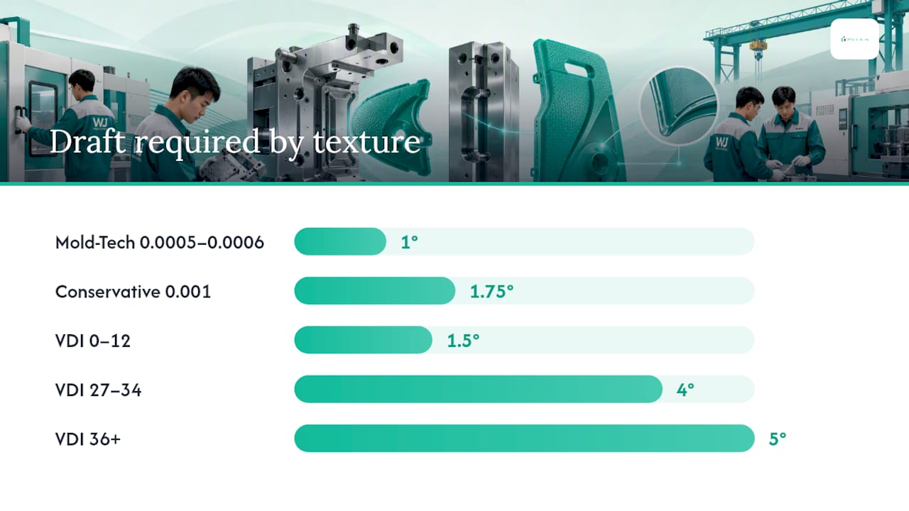
A more conservative guideline used in some tooling shops is roughly 1.5°–2° of draft per 0.001" of texture depth. It produces a slightly steeper draft recommendation than the Mold‑Tech baseline, and many toolmakers default to it when they are uncertain about resin behavior or when the part geometry includes any risk of drag.
Statistic to remember: industry mapping charts built around VDI grades put this into rough bands: VDI 0–12 (fine, near‑gloss textures) needs about 1°–2° of draft; VDI 27–34 (medium stipple and leather‑grain finishes) needs roughly 3°–5°; VDI 36 and above (deep, coarse textures) often needs 5° or more. Treat those as starting points from vendor charts, not guaranteed outcomes for every resin and geometry.
A working sequence for applying either rule looks like this:
None of these numbers account for shrink‑toward features, high‑shrink resins, or mechanical action like lifters. Those factors push the required draft higher still, sometimes substantially, and that is where a lot of first‑time designers get burned.
Resin choice changes everything about how a textured wall releases from steel. Amorphous resins like ABS, polycarbonate, and PC/ABS blends shrink less and more predictably, so the Mold‑Tech baseline rule tends to hold up well. Semi‑crystalline resins, including polypropylene, nylon, and POM, shrink more and less uniformly as they cool, which tightens their grip on textured steel and often demands draft above the standard recommendation.
Geometry matters just as much as resin. A deep rib with texture applied to its sidewalls behaves very differently from a flat exterior panel, because thin, tall features cool faster near the surface and lock onto texture detail before the core has fully solidified. Wall thickness transitions, boss placement, and feature orientation relative to the mold's opening direction all shift how much draft a given texture depth actually needs.
A few practical adjustments worth building into your design reviews:
Pro Tip:When a part mixes amorphous and semi‑crystalline resin options for different production runs, design the mold to the semi‑crystalline draft numbers from day one. It costs nothing at the design stage and saves a re‑cut if the resin changes later in the program.
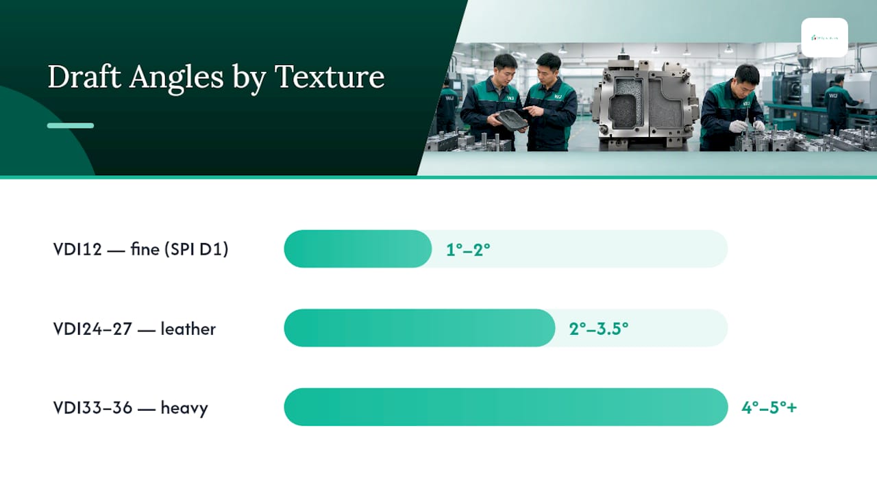
Exact numeric conversion between these three systems does not exist, and anyone who hands you a clean one‑to‑one table is oversimplifying. VDI measures roughness. Mold‑Tech sells named patterns with proprietary depth profiles. SPI covers only the lower end of the roughness spectrum and was never designed to describe heavy textures at all. What you can build is a conservative working map that keeps you safely on the high side of draft requirements.
A few example mappings worth keeping on hand for RFQ conversations:
The one unit conversion worth memorizing: 0.001 inch equals 25.4 microns. Most Chinese toolmakers quote texture depth in microns, while American engineering drawings default to thousandths of an inch, and misreading that conversion by a factor of ten is a surprisingly common and completely avoidable mistake on cross‑border projects.
Not every surface on a molded part carries the same draft risk, and treating them all identically wastes draft budget where it is not needed and starves it where it is critical.
Pro Tip:Ask your toolmaker to soften the texture transition at every lifter and slide line rather than running a hard boundary. It is a small tooling detail that prevents the sharp visual seam that shows up under raking light on finished parts.
Most textured mold surfaces get their finish through EDM (electrical discharge machining), which erodes the steel surface using electrical sparks to reproduce a texture pattern etched onto an electrode, or through chemical engraving processes. Both methods reproduce fine detail well on small to medium cavities, but transfer fidelity can drop off across large cavity surfaces, where inconsistent spark gaps or acid exposure time leave visibly uneven texture depth from one end of the tool to the other.
Quality control steps worth requiring in any RFQ to a Chinese mold supplier:
Engineering teams recommend locking down these items before quoting: chosen standard and grade (VDI, Mold‑Tech, or SPI), units (inches or microns), per‑zone draft targets, texture exclusion zones on ribs and bosses, and required trial‑shot acceptance criteria. Request digital texture proofs and a signed sample before production tooling starts.
| Checklist item | Why it matters |
|---|---|
| Standard and grade named explicitly | Prevents VDI‑to‑Mold‑Tech misreadings between engineering and the shop floor |
| Draft targets per zone, not per part | Ribs, cores, and lifters need different numbers than flat walls |
| Trial shot and texture card sign‑off | Catches transfer inconsistency before full production tooling is cut |
Engage tooling engineering during the prototype to production handoff, not after the mold is already quoted.
Until trial shots confirm otherwise, use these as safe starting points: shallow texture (VDI 0–12) at 1.5°–2°; medium texture (VDI 24–34) at 3°–5°; deep texture (VDI 36+) at 5°–7°. Push every number higher on shrink‑toward features and semi‑crystalline resins, and always validate against a real trial shot before cutting final steel.
I have seen the same failure pattern repeat across projects that otherwise had solid engineering behind them: a designer specifies a VDI grade on the drawing, the toolmaker quotes against a Mold‑Tech pattern with a different actual depth, and nobody catches the mismatch until the first trial shot shows drag marks on every rib. It is rarely a competence problem. It is a communication gap between two texture‑naming systems that were never meant to be interchangeable.
The second recurring mistake is treating draft as a single number for the whole part instead of a per‑feature decision. A part can pass overall dimensional inspection while still scuffing badly on one lifter face, because the global draft angle satisfied the flat walls but never accounted for that feature's actual ejection path.
The fix costs almost nothing relative to a re‑cut: require a single trial shot and a signed texture card before committing to production steel, and treat that sign‑off as a hard gate, not a formality. Review WJ Prototypes' injection molding workflow guidance for how that gate fits into a broader prototype‑to‑production sequence.
— Nas
Getting texture and draft right on the first tool run comes down to specifying the correct standard, converting conservatively between systems, and confirming the result with a physical trial shot rather than a spreadsheet. WJ Prototypes' CNC machining materials page and broader injection molding services in China are built around exactly this kind of DFM back‑and‑forth, where texture depth, draft angle, and resin shrinkage get resolved before steel gets cut, not after.
VDI 3400 is a standardized roughness classification system with numbered grades, while Mold‑Tech is a commercial brand offering named texture patterns with its own published depth and draft data.
Start with the Mold‑Tech ratio of roughly 1° per 0.0005"–0.0006" of texture depth, cross‑check against the VDI grade band chart, then increase draft for shrink‑toward features, semi‑crystalline resins, or moving tool components like lifters.
Castings typically use a different draft range than injection molded plastics, generally 1°–3° for sand and die castings depending on part depth and finish, since metal shrinkage and mold release behave differently from thermoplastics.
Slash China Mold Costs: 4 DFM Moves to Design Out Undercuts
Setting Tolerances Without Overpaying for Chinese Mold Tooling
Mastering Injection Molding Workflow for Precision Prototyping
The Real Cost of Undercuts in China Tooling Budgets
SERVICES
RESOURCES