


- Room 1807, Unit 9, Building 2, Shangxing Commercial Street, Shangde Road, Shangxing Community, Xinqiao Subdistrict, Bao'an District, Shenzhen City, China
CONTACT US

WhatsApp

Aerospace & UAV
WJ Prototypes is your 3D manufacturing partner from prototype to large scale production.
Consumer Electronics
New Product Introduction Solutions for Consumer Electronics.

Robotics & Automation
Need some assistance bringing your robotic device or parts from the sketch-board to reality?
Medical Devices
The medical industry needs high quality, dependable and safe parts and products.
Automotive
New Product Introduction Solutions for Automotive
Industrial Machinery
The main purpose of industrial prototyping is to take the product from drawings into the real world.

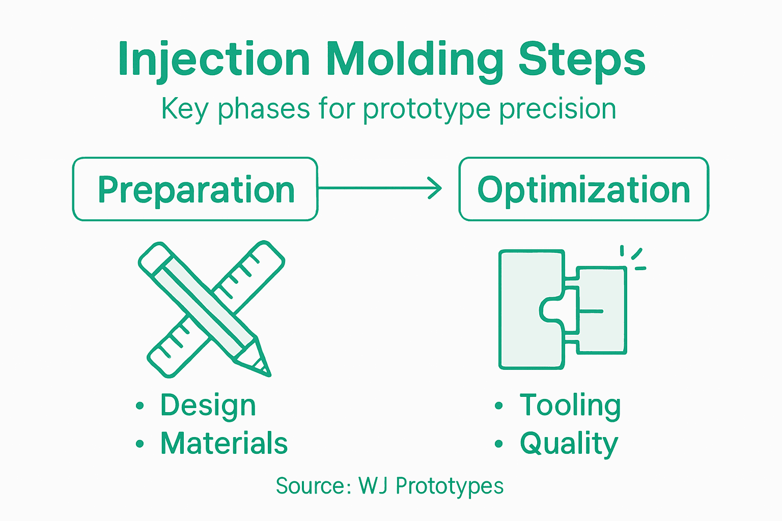
Choosing the right part design and materials is where every successful injection moulding project begins for aerospace and automotive engineers. The demands of creating reliable prototypes and controlling costs are higher than ever in competitive American, European, and Asian manufacturing environments. This guide will show you how to address critical part geometry and select polymeric and composite materials to improve prototyping efficiency while preventing expensive redesigns and wasted production cycles.
| Key Point | Explanation |
|---|---|
| 1. Focus on Part Design | A well-designed part must have uniform wall thickness to avoid defects such as warping and internal stress concentrations. |
| 2. Select Appropriate Materials | Choose materials based on performance requirements; consider factors like temperature resistance and biocompatibility for specific applications. |
| 3. Calibrate Injection Moulding Machine | Correct clamping force and temperature settings are crucial for preventing defects and ensuring part quality during production. |
| 4. Monitor Production Parameters | Continuous monitoring of melt temperature and injection pressure during production helps identify issues before they lead to scrap. |
| 5. Perform Comprehensive Inspections | Conduct detailed inspections on finished parts to ensure they meet design specifications and identify any moulding issues early in the process. |
This step forms the foundation of your entire injection moulding project. Getting your part design and material selection right before you commit to tooling saves you from costly iterations and delays. You'll work through the design constraints, functional requirements, and material properties that directly affect how your prototype performs and how efficiently it manufactures.
Start by examining your part's geometry with manufacturability in mind. Injection moulding places specific demands on part design that differ from other manufacturing processes. You need to consider uniform wall thickness throughout your component because varying thicknesses create cooling problems, internal stress concentrations, and potential warping. Areas where thick and thin sections meet cause the thicker sections to cool more slowly, creating weak spots and dimensional inconsistencies. Aim for wall thicknesses between 1.5 and 3 millimetres for most applications, adjusting based on your material choice and part complexity.
Material flow is equally critical to your success. When molten plastic enters the mould, it follows specific paths determined by gate placement and part geometry. Sharp corners, deep pockets, and long thin sections force the material to travel further and cool before completely filling the cavity, leading to incomplete parts or surface defects. Think about where material needs to travel and how it fills the mould cavity. Draft angles, typically 1 to 3 degrees, allow parts to eject cleanly without damaging the mould or the component itself. Undercuts that trap material should be avoided unless you can justify the added mould complexity and cost.
Now shift your focus to material selection, which determines your part's performance characteristics and processing requirements. Injection moulding produces complex, high-precision parts using polymeric and composite materials spanning thermoplastics, thermosets, elastomers, and composites with fibres or additives. For aerospace and automotive applications, your choice becomes even more critical. Thermoplastics like polycarbonate, acrylonitrile butadiene styrene, and polyetheretherketone offer excellent strength-to-weight ratios and can be reprocessed, making them ideal for precision prototyping. Fibre-reinforced composites increase stiffness and thermal resistance without adding significant weight, which directly addresses your industry's demands for lighter, more durable components.
Consider the specific performance requirements your prototype must meet. Does it need to withstand high temperatures, harsh chemicals, or extreme vibration? Will it face repeated stress cycles in service? Does dimensional stability matter more than impact resistance? Injection moulding material selection involves choosing from thermoplastics, elastomers, and thermosetting resins based on mechanical properties, durability, and environmental resistance. For prototype validation in demanding sectors like aerospace, you might select carbon-fibre reinforced nylon for its rigidity and thermal stability. For automotive under-bonnet components, glass-filled polyester delivers the chemical resistance and temperature performance needed. Medical device applications often require materials meeting biocompatibility standards and sterilisation compatibility.
Here is a comparison of common injection moulding materials and their typical applications:
| Material Type | Key Strengths | Common Applications |
|---|---|---|
| Polycarbonate | Impact resistance, clarity | Automotive lenses, housings |
| ABS (Acrylonitrile Butadiene Styrene) | Processability, toughness | Electronics, prototypes |
| Polyetheretherketone (PEEK) | High heat, chemical resistance | Aerospace parts, gears |
| Glass-filled Polyester | Chemical resistance, stability | Under-bonnet auto components |
| Carbon-fibre Reinforced Nylon | Rigidity, thermal stability | Aircraft interiors, brackets |
| Medical-grade Polypropylene | Biocompatibility, sterilisation | Medical devices, labware |
Sourced materials from manufacturers in China offer competitive pricing without compromising quality when you select suppliers with proper certifications and quality controls. Many globally recognised manufacturers source their injection-moulded components from Chinese facilities because the infrastructure for precision polymer processing is mature and well-developed. However, material quality varies significantly, so specify your material grades precisely, including fibre length, additives, and processing parameters in your design documentation.
Pro tip: Build in a small test cavity or witness mark into your mould design to verify material flow and cooling behaviour before committing your production mould; this single feature catches design flaws that would otherwise result in scrapped parts and expensive rework.
This step bridges the gap between design and production, transforming your carefully planned part into reality through precision tooling and machine calibration. Your mould must be manufactured to exacting tolerances, and your injection moulding machine must be configured perfectly to achieve consistent, high-quality prototypes. Getting this right determines whether your first run produces usable parts or costly scrap.
Start with your mould preparation. The tooling you've commissioned from your supplier arrives ready for installation, but you need to inspect it thoroughly before mounting. Check that cavity and core configurations match your design specifications exactly. Examine all surfaces for any defects, scratches, or damage that could transfer to your parts. Verify that precise dimensional tolerances have been achieved on critical features and that gate locations align with your material flow analysis from the previous step. Run your fingers gently over the mould surfaces to feel for any rough spots that might cause drag or premature wear. Test the mould halves together to ensure they close smoothly with even clamping pressure across the entire parting line. A mould that doesn't mate perfectly will leak material, creating flash on your parts and producing inconsistent dimensions.
Now focus on installing the mould securely into your injection moulding machine. Position the mould carefully between the machine's platens, ensuring it seats fully and evenly. Tighten the clamping bolts in a cross pattern, alternating sides to maintain balanced pressure across the mould. Many operators skip this step carelessly, but uneven clamping introduces stress that distorts the mould cavity and ruins part quality. Once secured, close the machine's safety guards and begin the critical calibration process. You'll adjust the clamping force first, setting it high enough to prevent material flash but not so excessive that it damages the mould. For precision prototyping in aerospace and automotive applications, this balance becomes crucial because even minor flash affects fit and function.
Temperature control forms the backbone of successful injection moulding. Thermal conditions in the barrel and mould ensure consistent operation by maintaining material at the precise viscosity needed for optimal flow. Set your barrel temperature zones progressively from the feed section toward the nozzle, typically increasing temperature as material moves forward. The exact temperatures depend on your chosen material, but most thermoplastics require 200 to 280 degrees Celsius. Programme your mould temperature controller to maintain the cavity and core at the correct temperature, usually 40 to 80 degrees Celsius for proper cooling. Allow the machine to reach thermal equilibrium for at least 20 to 30 minutes before attempting your first injection. This patience pays dividends because thermal drift during early cycles causes dimensional variation that wastes material and time.
Calibrate your injection parameters next. The screw speed, injection pressure, and hold pressure form an interconnected system that determines how material fills your mould. Start with conservative settings and increase gradually, monitoring part quality after each adjustment. Injection speed should fill the cavity completely before material cools too much, typically between 30 and 100 millimetres per second depending on your part complexity. Injection pressure provides the force to overcome material resistance and fill thin sections, generally ranging from 60 to 120 megapascals. Hold pressure maintains dimensional stability as material cools in the mould, usually set slightly lower than injection pressure. Cooling time varies significantly based on wall thickness and material conductivity, but for most prototypes you'll need 10 to 60 seconds before ejecting parts safely.
Pro tip: Run a series of test shots with cavity pressure monitoring before committing to your full production run, as this reveals exactly where your material fills first and last, allowing you to adjust gate location or injection parameters to eliminate voids and surface defects before wasting material and time on hundreds of parts.
Now that your machine is calibrated and your first test shots are running, the real work begins. Optimising your process parameters transforms occasional good parts into consistent, reliable prototypes that meet your specifications every single time. This step separates mediocre production from precision manufacturing, directly impacting your timeline and budget for aerospace and automotive validation work.
Start by understanding which parameters control which outcomes. Melt temperature affects how easily material flows through your mould, but too high and you risk degrading the polymer, too low and you get incomplete fills and weak parts. Mould temperature influences cooling rates and part shrinkage, with higher temperatures producing better surface finish but longer cycle times. Injection speed determines how quickly material enters the cavity, affecting pressure spikes, gate shear, and material orientation. Holding pressure maintains dimensional stability as the material cools, compensating for volumetric shrinkage that occurs as polymers solidify. Cooling time directly impacts your production rate, so finding the absolute minimum cooling required without causing dimensional drift or internal stresses becomes critical. Critical injection moulding process parameters affect melt temperature, mould temperature, injection speed, and holding pressure, each influencing material flow, cooling rates, residual stresses, and surface quality.
The table below summarises process parameters and their primary effects in injection moulding:
| Parameter | Effect on Part Quality | Risk if Incorrect Setting |
|---|---|---|
| Melt Temperature | Flow, complete cavity fill | Degradation or short shots |
| Mould Temperature | Cooling rate, surface finish | Warping or surface defects |
| Injection Speed | Fill pattern, orientation | Voids or flash |
| Holding Pressure | Dimensional stability | Sink marks or distortion |
| Cooling Time | Final dimensions, strength | Incomplete curing or warpage |
Begin optimisation by adjusting one parameter at a time while holding others constant. This methodical approach reveals cause and effect relationships instead of confounding results. If your parts show gate vestige or sink marks, increase holding pressure incrementally and monitor the effect on part dimensions. If you observe warping or dimensional inconsistency, adjust mould temperature upward by 5 degrees Celsius and run ten consecutive parts to see if stability improves. If parts exhibit short shots or incomplete filling, raise melt temperature by 5 to 10 degrees Celsius, then verify that surface finish doesn't degrade. Record every adjustment and its results in a process log that becomes invaluable when you transition from prototyping to production.
For systematic optimisation across multiple parameters, techniques like Design of Experiments and Taguchi methods identify optimal settings to reduce cycle time whilst improving dimensional stability and surface finish. These statistical approaches avoid the trap of randomly adjusting parameters and hoping for improvement. If you're producing dozens of prototypes, the investment in running a structured DOE study pays enormous dividends by revealing interactions between parameters that simple one-at-a-time adjustment cannot capture. For instance, you might discover that a specific combination of melt temperature and injection speed produces superior dimensional stability compared to either parameter optimised individually.
Focus relentlessly on reducing cycle time without sacrificing quality. Every second of cooling time you eliminate multiplies across your entire prototype run. If you can drop your cycle from 45 seconds to 40 seconds, that's an 11 percent improvement in throughput. But this demands precision. Pushing cooling time too aggressively introduces warping and dimensional drift that forces scrap parts and rework, ultimately wasting more time than you saved. Your objective becomes finding the sweet spot where parts cool sufficiently for stable dimensions and adequate mechanical properties, but no longer.
Monitor part quality metrics continuously during optimisation. Measure critical dimensions with digital calipers on every tenth part, track surface finish visually, inspect for flash and gate vestige, and perform periodic mechanical testing if your application demands it. Many manufacturers batch their quality checks, measuring only end-of-run parts, but this approach misses thermal drift that occurs mid-run. Aerospace and automotive sectors demand consistency, so catching parameter drift early prevents entire batches of out-specification parts.
Pro tip: Create a parameter window document that records the acceptable ranges for every process variable on your specific machine and mould, including minimum and maximum melt temperature, mould temperature, injection pressure, hold pressure, and cooling time, then use this as your reference guide for future production runs to maintain consistency and avoid repeating optimisation work.
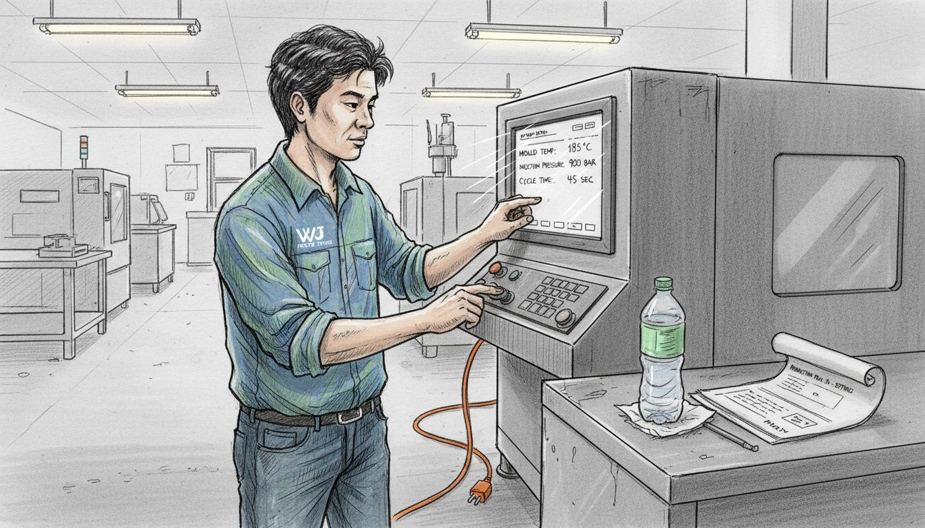
Real-time monitoring transforms injection moulding from a process you hope works into one you actively control. During production, countless variables shift subtly—material temperature drifts, wear develops on mould surfaces, and ambient humidity fluctuates. Your job during this step is to catch these changes before they produce defective parts, maintaining the consistency that aerospace and automotive engineers demand from every single component.
Begin by establishing your baseline measurements before the production run starts. Record melt temperature, mould temperature, injection pressure, holding pressure, and cooling time on your first successful part. Take this baseline and photograph critical part dimensions using your digital calliper or measuring device. Note the surface finish quality, gate vestige appearance, and any subtle rippling or flow lines. This baseline becomes your reference for detecting drift. As your run progresses, measure critical dimensions on every tenth part, alternating between different features to catch both systematic shift and random variation. Watch for signs that something is changing. Sink marks deepening near ribs suggest mould temperature climbing. Increasing gate vestige indicates pressure dropping. Dimensional creep in one direction signals thermal growth or mould wear.
Monitor the process parameters continuously using your machine's control display. Monitoring injection moulding operations involves checking melt temperature, mould temperature, injection speed, and pressure to detect anomalies impacting quality, with consistent recording and adjustment helping control defects like warpage, sink marks, and short shots. Rather than trusting the machine's display alone, record parameters manually every thirty minutes into your production log. You'll spot patterns this way. Perhaps your melt temperature edges upward as the material hopper empties. Perhaps injection pressure gradually declines as the screw wears slightly. Catching these trends early allows you to make micro-adjustments that prevent entire batches from drifting out of specification.
Implement statistical process control thinking into your quality monitoring. Track your dimensional measurements on a simple chart, plotting each result chronologically. When you see five consecutive parts drifting in one direction, that's your signal to investigate and adjust. Explainable AI techniques analyse sensor data and process variables to classify part quality in real-time, providing insights into critical parameters affecting defects. If your facility has access to advanced monitoring systems with sensors feeding data to analysis software, these tools accelerate anomaly detection. However, even without sophisticated technology, disciplined manual recording and basic statistical thinking deliver remarkable results. Many manufacturers using Chinese injection moulding services rely on partner facilities with excellent monitoring practices, but verifying that your supplier maintains consistent process control remains your responsibility.
Inspect parts visually and tactilely throughout the run, not just at the end. Short shots, incomplete fills, appear immediately. Flash creeping across the parting line signals increasing clamping force issues or mould degradation. Rough spots developing on surfaces indicate cooling channel problems or material degradation. The moment you notice anything unusual, stop production, investigate the cause, and correct it. This discipline prevents catastrophic failures where an entire batch becomes scrap. Keep a defect log recording what you observed, when you observed it, what adjustment you made, and how the parts improved. Over time, this log becomes invaluable institutional knowledge about your specific mould and material combination on your particular machine.
Pro tip: Establish control limits on a simple spreadsheet tracking your three most critical dimensions across production runs, then plot new production data against historical ranges to instantly spot when parts drift outside acceptable variation, allowing you to react before scrap accumulates instead of discovering problems during post-production quality inspection.
Your injection moulding run is complete, and now comes the critical final step that separates acceptable prototypes from those destined for scrap. Comprehensive inspection and quality assurance determines whether your parts meet design specifications and functional requirements or whether you need to rework your process. This step protects your aerospace and automotive validation work, ensuring every component you submit for testing or assembly performs as intended.
Begin with dimensional inspection using calibrated measuring equipment. Select ten parts randomly distributed throughout your production run, representing early, middle, and late cycle parts. Measure every critical dimension specified on your engineering drawing using digital callipers, micrometres, or coordinate measuring machines depending on tolerance tightness. Record each measurement against the design specification and tolerance band. Look for systematic patterns. Do early-run parts tend larger than late-run parts? This suggests mould temperature drift or thermal growth. Are dimensions randomly scattered across the tolerance range? This indicates poor process stability. Inspection of finished parts ensures compliance with design specifications and functional requirements through standardised testing, with tolerances and acceptance conditions for plastic moulded parts including dimensional and geometrical measurements. Compare your results to ISO 20457:2018, which specifies acceptance criteria for injection moulded components worldwide.
Move beyond simple dimensional checking to assess visual and surface quality. Examine parts under good lighting for flash at the parting line. Run your fingers across critical surfaces to feel for roughness or flow lines that might affect assembly fit. Look for sink marks, voids, or weld lines where material streams converge. Inspect gate areas for excessive vestige or stress concentration points. These visual defects rarely appear randomly. They follow patterns that trace back to process parameters or mould design. Short shots indicate incomplete filling, usually caused by inadequate melt temperature or injection pressure. Warping suggests uneven cooling or excessive holding pressure. Surface quality problems typically stem from screw speed degradation, material degradation, or mould surface wear.
Perform mechanical property testing on representative samples if your application demands it. Quality assurance includes dimensional checks, visual inspection for surface defects, and mechanical property testing to validate process capability and conform to customer and regulatory requirements. Pull tests, impact tests, or hardness measurements confirm that your material processing hasn't degraded polymer properties. For aerospace and automotive applications, this testing becomes non-negotiable because structural integrity depends on material properties matching your design assumptions. Many Chinese injection moulding facilities can perform basic mechanical testing, or you can arrange independent laboratory testing if required.
Document your inspection results thoroughly. Create a quality record for each production batch recording which parts were inspected, what measurements were taken, which parts passed acceptance criteria, and which parts require rework or scrap. This documentation becomes your proof that quality control was exercised and provides traceability if issues emerge later. Establish clear acceptance criteria before you begin inspecting. Perhaps you'll accept all parts within nominal dimensions plus tolerance. Perhaps you'll reject any part showing flash larger than 0.3 millimetres. Whatever your criteria, document them and apply them consistently. Inconsistent application of standards creates more problems than occasional acceptance of marginal parts.
If you discover systematic quality failures, resist the urge to simply rework the affected parts and continue. Instead, trace the root cause. Did your process parameters drift? Did mould wear develop? Did material properties change? Understanding why parts failed guides corrective action that prevents the same failure in future production. This investigation mindset transforms quality assurance from paperwork compliance into genuine process improvement.
Pro tip: Establish a first article inspection protocol where you measure and test twenty consecutive parts from the beginning of your production run before approving the remaining batch for release, catching process drift and mould wear issues early rather than discovering problems after the entire run completes.
Injection moulding for precision prototyping demands meticulous attention to design, material selection, process optimisation, and quality control as detailed in the article. The challenges of achieving consistent part quality, controlling thermal and pressure variables, and meeting stringent aerospace or automotive standards can feel overwhelming. You need a reliable partner who understands the delicate balance between manufacturability and performance while delivering rapid turnaround and cost-effective solutions.
At WJ Prototypes, we specialise in turning complex injection moulding projects into successful outcomes. Our ISO certified manufacturing processes incorporate advanced tooling preparation, exacting parameter calibration, and rigorous quality assurance protocols. Whether you require prototypes with high dimensional stability or small to medium production runs with tight tolerances, our team of experienced engineers and state-of-the-art technology have you covered. Explore how our comprehensive Injection Moulding Services can help you overcome prototyping hurdles, reduce costly rework, and accelerate your product validation.
Take control of your precision prototyping today and partner with experts who deliver consistent, high-quality injection moulded parts. Get your instant quote at WJ Prototypes and transform your design into reality with confidence.
Begin by examining your part's geometry with manufacturability in mind. Ensure uniform wall thickness between 1.5 and 3 millimetres is maintained to prevent cooling issues and warping.
Select materials based on your part’s performance requirements, such as high strength or chemical resistance. Consider thermoplastics like Polycarbonate or ABS, which offer excellent properties for prototypes in various industries.
Inspect your mould thoroughly for any defects that could affect part quality. Ensure that cavity and core configurations match your design specifications precisely before mounting it in the injection moulding machine.
Focus on melt temperature, mould temperature, injection speed, holding pressure, and cooling time to maintain consistent quality. Record these parameters regularly to identify any drifting trends that could lead to defects.
Perform dimensional inspections on a random sample of parts and assess visual quality for defects. Document measurements against specifications and note any systematic patterns that may require process adjustments.
Stop the production run to investigate the root cause of any defects you observe, such as short shots or warping. Implement corrective actions to prevent recurrence, ensuring that quality remains consistent throughout future runs.
Injection Molding Guide: Achieve Accurate Prototypes Fast
What Is Injection Molding? A Complete Guide to Moulding Processes
InjectiInjection Molding Step by Step | How to Find One in China
Benefits Of Precision Injection Molding Services - Why Choose China?
SERVICES
RESOURCES


