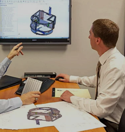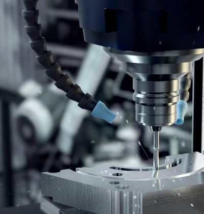
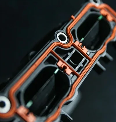
preventing-micro-porosity-in-high-volume-die-casting
Position:
/

Preventing Micro-Porosity in High-Volume Die Casting

2026-08-07 10:10:22

preventing-micro-porosity-in-high-volume-die-casting.jpeg


TL;DR:
Micro-porosity in die casting results from trapped gases and shrinkage during solidification, which can be managed effectively. Combining vacuum-assisted filling, pressure intensification, gating redesign, mold rigidity control, and directional solidification minimizes porosity and improves part quality. Proper application of these techniques leads to more consistent, high-quality high-volume castings.

Micro-porosity is defined as a network of fine, dispersed pores that form between dendritic solidification networks during metal solidification, distinct from the rounded gas pores caused by trapped air. Knowing how to prevent micro-porosity in high-volume Chinese die casting projects is the difference between consistent, structural-grade output and a scrap rate that kills margins. The root causes fall into three controllable categories: gas entrapment, shrinkage during solidification, and mold design failures. Techniques like vacuum-assisted die filling, intensification pressure between 35–1000 bar, and directional solidification through strategic riser and chill placement address each cause directly. This guide covers the specific methods, parameter ranges, and design decisions that production engineers use to keep porosity out of high-volume runs.

How to prevent micro-porosity in high-volume Chinese die casting projects with vacuum and pressure

Vacuum-assisted die filling is the most direct method for removing gas from the mold cavity before metal enters. Vacuum valves extract trapped air prior to filling, which reduces both the size and quantity of gas pores in the finished casting. Without evacuation, air compressed by the incoming metal front has nowhere to go and becomes locked inside the part.

Intensification pressure works at the opposite end of the fill cycle. Once the cavity is full, intensification pressure between 35–1000 bar compacts residual gases and forces additional molten metal into shrinking zones during solidification. This compensates for volumetric contraction, which is the primary driver of shrinkage porosity in high-pressure die casting (HPDC). Studies from 2025–2026 confirm that applying intensification pressure improves tensile strength and elongation by lowering pore volume in the final part.

The two techniques work best together, not independently. Vacuum removes gas bubbles while pressure compresses whatever residual gas remains and supports continuous feeding during solidification. Running vacuum without adequate intensification leaves shrinkage porosity unaddressed. Running intensification without vacuum means the pressure is compacting gas that could have been removed entirely.

Pro Tip: Set vacuum activation to trigger 0.1–0.2 seconds before the plunger reaches high-speed injection. Late activation leaves air in the cavity; early activation wastes cycle time without improving evacuation.

Key process parameters to monitor when combining these techniques:

  • Vacuum level: target below 50 mbar absolute pressure in the cavity before injection
  • Intensification pressure onset: apply within 20–50 milliseconds of cavity fill completion
  • Pressure hold time: maintain until the gate solidifies to prevent backflow
  • Valve response time: use fast-acting vacuum valves rated for the specific shot weight and fill time

Get FREE DFM & Quote

Explore competitive Die Casting Services with expert support from WJ Prototypes.

Whether you're comparing suppliers or looking to optimize costs, our team can help you evaluate the best option for your project.

👉 Request A Quote now or email us at info@wjprototypes.com to get started.


How does gating design affect porosity and thermal balance?

Gating system design controls how metal enters the cavity, and poor design creates two porosity drivers at once: turbulence and thermal gradients. Turbulent metal flow folds air into the melt stream, creating gas pores. Uneven temperature distribution creates localized hot spots where metal stays liquid longer and shrinks last, with no feeding path to compensate.

micro-porosity-prevention-steps.jpeg

Redesigning gating systems by closing redundant feed branches and adding flow-regulating bottlenecks reduces thermal gradients by more than 50%. That number matters because a 50% reduction in thermal gradient translates directly to more uniform solidification across the cavity. Uniform solidification means every section of the part reaches the solid state in a controlled sequence, leaving fewer isolated liquid pools that shrink without feed.

Thermal imbalance between fixed and movable dies contributes to localized hot spots that cause porosity and accelerate die wear. Thermographic analysis of redesigned gating systems shows temperature stabilization across both die halves after modification. A more balanced die runs longer between maintenance cycles, which matters enormously in high-volume production where downtime is expensive.

Practical gating modifications that reduce porosity:

  • Close secondary feed branches that create competing flow fronts and air entrapment zones
  • Add flow bottlenecks at branch junctions to regulate fill velocity and reduce turbulence
  • Position overflows at the last-fill zones to capture air pushed ahead of the metal front
  • Use finite element modeling (FEM) to simulate temperature distribution before committing to tooling changes
  • Verify thermal balance with thermographic imaging after the first production run

Pro Tip: Map the thermal profile of your die after 50 shots at steady state, not at startup. Startup temperatures are misleading. Steady-state thermography shows the real hot spots that cause porosity in production.

Does mold rigidity affect micro-porosity formation?

Mold rigidity is the most frequently overlooked variable in porosity control. Insufficient die stiffness causes wall movement under high injection pressure, which transiently increases cavity volume during the fill phase. When the cavity expands, the incoming metal must fill a larger space than designed. That extra volume draws in molten metal from adjacent zones and traps gas at the expansion boundary.

measuring-die-casting-mold-component.jpeg

The fix is not always a cavity redesign. Engineers need to audit the full mold assembly, including support pillars, parting surface flatness, and tie bar load distribution. A cavity with excellent geometry but a flexing die shoe will still produce micro-porosity at high injection pressures.

Injection speed control works alongside mold rigidity to reduce gas entrapment. Plunger speeds between 1.7 and 3.4 m/s minimize turbulence and entrained gas during cavity fill. Speeds above this range increase the risk of air folding into the metal front, which creates gas pores that no amount of intensification pressure can fully eliminate.

Parameters to audit for mold rigidity and injection speed control:

  • Die shoe thickness and material grade relative to projected cavity pressure
  • Support pillar placement under high-pressure zones of the cavity
  • Plunger speed profile: slow first phase to fill the shot sleeve, fast second phase through the gate, controlled transition timing
  • Gate velocity: calculate from plunger speed and area ratio to confirm it falls within the non-turbulent range
  • Parting surface contact area: insufficient contact allows die breathing under pressure

What feeding design prevents shrinkage porosity clusters?

Directional solidification is the principle that metal should solidify from thin sections toward thick sections, with the thick sections fed last by a continuous liquid path. Strategic riser placement and chills achieve this by controlling where heat leaves the casting and in what sequence. When solidification runs in the wrong direction, thick sections freeze last without a feed path, and the shrinkage that occurs during contraction creates clustered micro-porosity.

Solidification simulation tools, including software like MAGMASOFT and ProCAST, let engineers verify the solidification sequence before cutting steel. The simulation identifies isolated liquid zones, called hot spots, that will shrink without feeding. Riser and chill placement then targets those zones specifically.

The steps for effective feeding design in high-volume die casting follow a clear sequence:

  1. Run solidification simulation to identify the last-to-freeze zones in the cavity
  2. Position risers adjacent to thick sections, sized to stay liquid longer than the section they feed
  3. Place metal or graphite chills against thick sections that border thin ones to accelerate local cooling
  4. Insulate risers where needed to extend their feed life during solidification
  5. Validate the modified design with a second simulation pass before tooling changes
Feeding elementFunctionBest placement
Insulated riserStays liquid to feed shrinking sectionsAdjacent to the thickest casting section
Metal chillAccelerates cooling in targeted zonesAgainst thick sections bordering thin walls
Graphite chillModerate cooling with thermal stabilityComplex geometries needing controlled gradient
Overflow wellCaptures cold metal and trapped airLast-fill zones at the cavity perimeter

Chills and risers work as a system. A chill placed against a thick section pulls heat out faster, which steers solidification toward the riser rather than away from it. That directed sequence eliminates the isolated liquid pools where shrinkage porosity clusters form.

Key Takeaways

Preventing micro-porosity in HPDC requires combining vacuum evacuation, intensification pressure, gating redesign, mold rigidity control, and directional solidification into one integrated process.

PointDetails
Vacuum plus intensificationApply vacuum below 50 mbar before injection, then intensification pressure at 35–1000 bar during solidification.
Gating redesign cuts gradientsClosing redundant feed branches reduces thermal gradients by more than 50%, cutting turbulence and hot spots.
Mold rigidity mattersAudit die shoe stiffness and support pillars, not just cavity geometry, to prevent wall movement under pressure.
Control plunger speedKeep injection plunger speeds between 1.7 and 3.4 m/s to minimize turbulent air entrapment.
Directional solidificationUse simulation tools to place risers and chills so thick sections solidify last with a continuous feed path.

What I've learned from watching porosity problems repeat themselves

The pattern I see most often in high-volume Chinese die casting projects is this: engineers fix one variable and expect the porosity problem to disappear. They add vacuum, the numbers improve slightly, and then the team declares success. Six months later, scrap rates climb again because the gating system was never addressed, or the die shoe is flexing under the new injection pressure they added to compensate.

Micro-porosity is not a single-cause defect. It is a system failure. The metal casting methods that consistently produce low-porosity parts treat mold design, process parameters, and feeding as one integrated problem, not three separate ones.

The second mistake I see is skipping defect mapping. Engineers run X-ray or CT scans on rejected parts but never build a spatial map of where porosity clusters appear across a production run. That map tells you whether the problem is thermal (hot spots in consistent locations), mechanical (wall movement under pressure), or process-driven (injection speed variation between shifts). Without the map, you are guessing at root cause.

My honest recommendation: invest in solidification simulation before you cut steel, and invest in steady-state thermographic imaging after your first production run. Both tools pay for themselves in the first month of reduced scrap. The engineers who resist simulation because it adds lead time are the same ones spending three months chasing porosity defects in production.

— Nas

WJ Prototypes' precision machining for die casting quality

Controlling micro-porosity starts with the mold itself, and mold quality depends on the precision of every machined component inside it.

WJ Prototypes delivers CNC machined die components with the dimensional accuracy that high-pressure die casting molds require. From die inserts to support pillars and gating channels, tight tolerances on every component reduce the assembly flex that causes wall movement under injection pressure. WJ Prototypes also offers die casting services in China with process controls aligned to the vacuum, intensification, and thermal management techniques covered here. Contact the WJ Prototypes engineering team to discuss your production requirements and get a quote for your next high-volume project.

Get FREE DFM & Quote

Explore competitive Die Casting Services with expert support from WJ Prototypes.

Whether you're comparing suppliers or looking to optimize costs, our team can help you evaluate the best option for your project.

👉 Request A Quote now or email us at info@wjprototypes.com to get started.


FAQ

What causes micro-porosity in die casting?

Micro-porosity forms between dendritic solidification networks when shrinkage occurs without a continuous feed path, or when gas becomes trapped during cavity fill. It differs from rounded gas pores, which result from air entrapment alone.

What intensification pressure range reduces shrinkage porosity?

Intensification pressure between 35 and 1000 bar compacts residual gases and feeds molten metal into shrinking zones during solidification, reducing pore volume and improving mechanical properties.

How does gating redesign reduce porosity?

Closing redundant feed branches and adding flow bottlenecks reduces thermal gradients by more than 50%, which cuts turbulence, eliminates localized hot spots, and produces more uniform solidification across the cavity.

What injection plunger speed minimizes gas entrapment?

Plunger speeds between 1.7 and 3.4 m/s minimize turbulent air folding during cavity fill. Speeds above this range increase porosity risk regardless of vacuum or intensification settings.

How does directional solidification prevent micro-porosity clusters?

Directional solidification, achieved through riser and chill placement guided by simulation, ensures continuous feeding of thick sections as they contract, eliminating the isolated liquid pools where shrinkage porosity clusters form.


Recommended

Die Casting Materials | Custom Material For Die Casting - Get A Quote
Vacuum Casting Materials | List Of Material For Vacuum Casting
Guide To Vacuum Casting - Master Prototyping for Precision Parts
Why Choose Die Casting for High-Precision Manufacturing

Get FREE DFM & Quote

Explore competitive Die Casting Services with expert support from WJ Prototypes.

Whether you're comparing suppliers or looking to optimize costs, our team can help you evaluate the best option for your project.

👉 Request A Quote now or email us at info@wjprototypes.com to get started.