




- Room 1807, Unit 9, Building 2, Shangxing Commercial Street, Shangde Road, Shangxing Community, Xinqiao Subdistrict, Bao'an District, Shenzhen City, China
CONTACT US

WhatsApp


Contact Us
Our team is on stand by, waiting toassist you.

Videos
A large collection of educational videos and tutorials.

About Us
Learn about our company, leadership, and mission totransform manufacturing.

Privacy Policy
Applies to all personal information collected through and/or processed in connection.


Aerospace & UAV
WJ Prototypes is your 3D manufacturing partner from prototype to large scale production.

Consumer Electronics
New Product Introduction Solutions for Consumer Electronics.

Robotics & Automation
Need some assistance bringing your robotic device or parts from the sketch-board to reality?

Medical Devices
The medical industry needs high quality, dependable and safe parts and products.

Automotive
New Product Introduction Solutions for Automotive

Industrial Machinery
The main purpose of industrial prototyping is to take the product from drawings into the real world.


Surface roughness Ra is the arithmetic average of a surface profile’s deviations from its mean line, measured over a defined length and reported in micrometers or microinches. It is the default parameter for controlling how smooth or rough a machined surface is, because it is cheap to measure, universally understood, and good enough for most functional and cosmetic requirements. It has a real blind spot, though: Ra averages out a surface, so a single deep scratch or gouge can hide inside a perfectly acceptable number, which is why fatigue-critical and sealing surfaces often need a second parameter alongside it.
TL;DR:
- Ra values around 125 to 250 micrometers are suitable for non-critical surfaces like cast or forged parts, while finer finishes below 16 micrometers are necessary for bearing journals and optical mounts.
- Measurement settings such as cutoff length, evaluation length, and stylus tip radius significantly influence Ra results, requiring detailed documentation for consistency and reproducibility.
- Using Rz and RMS parameters provides better detection of deep flaws and peaks, especially for fatigue-critical or sealing surfaces, as Ra can mask isolated defects.
- Different standards and units (micrometers vs microinches) can cause discrepancies, so clearly specify the standard and measurement method on drawings.
- Achieving precise Ra requires aligning manufacturing processes and finishing methods with the intended functional application to avoid over-specification or unnecessary cost.
Ra is the arithmetic mean of the absolute value of every height deviation from the profile’s mean line, sampled across an evaluation length. The formula looks intimidating on paper: Ra = (1/L) ∫ |y(x)| dx, where L is the sampling length and y(x) is the height of the profile at position x above or below the mean line. In plain terms, take a trace of the surface, flip every valley up to match its matching peak, and average the whole thing. That single number tells you how far the surface, on average, strays from flat.
ASME B46.1 and ISO 4287 are the two standards that formally define Ra and govern how it gets sampled and reported. They are not identical twins. ASME B46.1 is the American reference most U.S. shops quote against, while ISO 4287 underpins European and much of the rest of the world’s practice. The math is functionally the same, but default cutoff lengths, evaluation lengths, and some secondary parameter definitions differ enough that a drawing calling out “Ra 32” without naming a standard is genuinely ambiguous.

Units matter just as much as the number itself. In the U.S., Ra is commonly reported in microinches (µin), with 32 µin, 63 µin, and 125 µin as familiar shop-floor values. Most of the rest of the world, and increasingly U.S. aerospace and medical work, uses micrometers (µm). The conversion is simple: 1 µm equals roughly 39.37 µin, so a 1.6 µm finish converts to about 63 µin, and a 0.8 µm finish lands near 32 µin.
A few notation habits are worth locking in on drawings and inspection reports:
Skipping the standard reference is one of the most common reasons a supplier’s inspection report and a customer’s expectation do not match, even when both sides measured the same physical part correctly.
A contact stylus profilometer drags a diamond tip across the surface at a constant speed and records vertical deflection as an electrical signal, which the instrument’s software converts into the roughness profile and calculates Ra from. It remains the workhorse method for Ra because it is fast, portable, and produces results that map directly onto decades of shop-floor experience and standards language.
The settings you record alongside the number matter as much as the number itself:
Optical and areal (3D) methods, using white-light interferometry, confocal microscopy, or focus variation, skip physical contact entirely and capture a full area rather than a single line trace. Areal instruments can compute Sa, the areal equivalent of Ra, along with functional parameters that a 2D stylus trace simply cannot see, and they do it without risking scratches on soft or delicate surfaces. The tradeoff is cost and, on very rough or deeply featured surfaces, occasional trouble resolving steep walls that a stylus tip would trace without issue.
Reported Ra values on the same part can shift by 20% or more depending on cutoff length and traverse direction alone. That is not an instrument defect. It reflects the fact that Ra is inherently sensitive to the sampling choices behind it, which is exactly why documenting those choices on the inspection record is not optional busywork.
A few practical limitations deserve attention regardless of which method you use. Stylus tips wear down over thousands of traces and start rounding off fine peaks, quietly biasing Ra low until someone catches it during calibration. Vibration from nearby equipment can inject noise into a trace on a sensitive setup. And measuring across a lay direction versus along it on a turned or ground part can produce noticeably different numbers from the same physical surface, which is why lay direction belongs in every measurement record, not just the drawing callout.
Ra tells you the average deviation across a surface; Rz and Rq tell you something closer to the worst case. Rz, the Mean Roughness Depth, averages the five largest peak-to-valley heights within the sampling length, which makes it far more sensitive to an isolated deep scratch or a single tall burr than Ra ever will be. Rq, often called RMS roughness, squares each deviation before averaging and taking the square root, which weights larger deviations more heavily than Ra’s simple absolute-value approach.
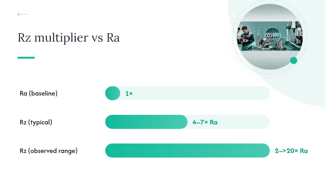
A widely repeated shortcut says Rz runs roughly four to seven times the Ra value for typical machined surfaces. That ratio holds reasonably well for conventional turning and milling, but it is genuinely just a rule of thumb, not a conversion you can bank on for critical tolerances. The actual multiplier swings from about 2:1 to well over 20:1 depending on the process, the cutting tool geometry, and the material, and no reliable universal conversion between Ra and Rz exists because the two parameters are measuring fundamentally different things. Treating that ratio as a formula on a fatigue-critical part is a mistake worth avoiding entirely.
Sa, the areal (3D) equivalent of Ra, extends the same averaging logic across a full surface area instead of a single line. It is part of the growing shift toward 3D areal characterization, alongside S-parameters that describe summit density, texture direction, and other functional traits a 2D trace cannot capture.
So when should you reach past Ra for something else?
Rz and other extreme-sensitive parameters exist precisely because Ra can mask the one flaw that actually causes a part to fail in service. Note also that ASME and ISO define some of these secondary parameters slightly differently, so a spec that mixes standards without naming which one governs each parameter is inviting a dispute later.
Picking a target Ra without understanding what that number feels and looks like in the shop leads to either an over-tight spec that inflates cost or a loose one that lets an unacceptable part through. The table below maps common bands to what you can expect to see and feel, along with the part features where each range typically applies.
| Ra Range | Appearance and Feel | Typical Applications |
|---|---|---|
| 125–250 µin (3.2 µm) | Visible tool marks, rough to the touch | Non-critical cast or forged surfaces, structural brackets |
| 63 µin (1.6 µm) | Visible feed lines but smooth under a fingernail | General-purpose machined surfaces, standard bores |
| 32–63 µin (0.8–1.6 µm) | Fine machining marks, smooth feel | Fine machined surfaces, moderate-tolerance fits |
| 16–32 µin (0.8 µm) | Near-mirror in raking light, very smooth | Press-fit bores, dynamic seal contact faces |
| Below 16 µin (0.8 µm) | Mirror-like, essentially glassy | Bearing journals, hydraulic components, optical mounts |
That general-purpose 125–250 µin band covers most cast or forged as-received surfaces and plenty of non-mating brackets. A 63 µin finish is the everyday default for machined parts that need to look intentional but do not touch anything moving, and it shows visible feed lines without feeling rough. Drop into the 32–63 µin band for surfaces going into a moderate-tolerance fit, and go below 16 µin only when you actually need it, which usually means grinding, honing, or lapping rather than any turning or milling operation.
The most expensive mistake in specifying Ra is calling out a mirror finish on a surface that will never be seen or touched by anything critical. Every step down in Ra typically means an added finishing operation, a longer cycle time, or both, so match the number to the actual function, not to what looks impressive on paper.
A drawing callout only works if the machinist, inspector, and customer all read it the same way. That starts with the surface texture symbol defined in ASME Y14.36, which places the Ra value, the applicable standard, and, when relevant, the lay direction and machining method directly on the checkmark-shaped symbol pointing at the surface.
A complete, defensible callout includes:
Specify Ra only where it actually drives function or appearance. A blanket callout applied to an entire part, “all surfaces 63 µin unless noted,” sounds efficient but almost always over-specifies non-critical faces while under-thinking the ones that matter. Break the part into functional zones instead: tight tolerances and fine finishes on bearing bores and sealing faces, looser and cheaper finishes everywhere else. That single habit, more than any other drafting practice, is what keeps quotes accurate and keeps arguments with your supplier from happening after the parts already shipped.
Pro Tip: Add a drawing note specifying the measurement method (stylus vs optical) and the standard used for reporting. A supplier measuring with an optical areal system and a customer measuring with a stylus trace can legitimately get different numbers on the identical part, and that note heads off the argument before it starts.
Reproducibility problems with Ra rarely come from a bad instrument. They come from undocumented setup choices that quietly shift the reported number from one measurement session to the next. A short checklist closes most of that gap:
The most common errors that undermine a Ra reading are avoidable with basic discipline. Taking a single trace and calling it representative is one of the biggest: a lone measurement can land on an unusually smooth or rough spot and misrepresent the whole surface, so multiple traces at different locations, averaged, give a far more honest number. Averaging across an obvious defect, like a chatter mark or a tool chip line, hides a localized problem inside a passable average. Using the wrong cutoff length for the roughness range being measured skews results in either direction. And skipping metadata entirely, most of all, is what turns a legitimate measurement dispute into a finger-pointing exercise months later.
Calibration deserves the same rigor. Stylus tips wear with use and gradually round off, biasing every subsequent reading low, so periodic verification against a certified roughness standard artifact catches drift before it corrupts a production run.
Pro Tip: Keep a calibration log tied to the specific stylus or objective in use, not just the instrument as a whole. Swap the tip, and the calibration history resets with it.
Every manufacturing process has a realistic Ra floor, and pushing past it usually means switching methods rather than fighting the current one. Finish turning and milling typically land in the 63–125 µin range with standard tooling, conventional grinding brings that down to roughly 16–32 µin, and honing or lapping can reach below 8 µin when a bore or flat face genuinely needs it.
A handful of levers move Ra without changing the process entirely:
The decision between tightening cutting parameters and adding a finishing operation almost always comes down to volume and target Ra. A single prototype might just need a slower final pass; a production run targeting a mirror finish is usually cheaper served by a dedicated grinding or lapping step than by chasing diminishing returns on feed and speed. WJ Prototypes’ surface finishing guidance covers this tradeoff in more depth for teams weighing machining time against a finishing operation.
Hitting a specified Ra consistently across a prototype run or a low-volume production order takes more than a well-maintained machine. CNC machining, grinding, and secondary finishing under ISO-certified quality processes, with surface-finish inspection built into the QA checkpoints between roughing, finishing, and final part release, are commonly run under professional manufacturing quality systems. That means a target Ra called out on a drawing gets checked against the actual standard specified, not assumed from feed and speed settings alone.
For readers weighing the machining and finishing decisions covered above, WJ Prototypes’ CNC machining process guidance breaks down how sampling and finishing choices carry through from design intent to a passable inspection report.
Function should drive the number, not habit. A default 63 µin callout on every drawing, whether the surface seals fluid or sits inside a bracket nobody will ever touch, wastes money on one and risks failure on the other. Second, treat measurement metadata as part of the spec, not paperwork: cutoff length, lay direction, and instrument type belong on the inspection record every time. Third, never lean on a single number for a surface where the worst point matters more than the average. Talk to your supplier about measurement method before the quote, not after the part ships.
— Nas
Meeting a tight Ra callout reliably takes real process control, not a lucky setup, and that is the specific gap CNC Machining Service at WJ Prototypes is built to close for prototype and low-volume orders. Between CNC machining, precision grinding, and post-process polishing, WJ Prototypes matches the finishing route to the actual Ra your part needs rather than defaulting to whatever the mill produces on its own. When requesting a quote, include your target Ra value with its unit and governing standard, which surfaces need inspection versus which are non-critical, and any sampling plan requirements for your inspection report. That level of detail, submitted through the instant quote system, lets WJ Prototypes’ ISO-certified process price the job accurately the first time instead of revising it after a failed inspection.
Two documents anchor almost every Ra conversation worth having: ASME B46.1 for definitions and reporting rules, and ISO 4287 for the international equivalent. For drawing symbols specifically, ASME Y14.36 governs how surface texture gets marked on prints. Instrument manufacturer application notes, including those from Bruker and KEYENCE, fill in the practical measurement details standards documents leave out.
A 0.8 µm Ra finish is a fine machined surface, roughly equivalent to 32 µin, typically achieved through fine turning, milling with light finishing passes, or light grinding. It falls in the range used for press-fit bores and dynamic seal faces where smoothness matters but a mirror finish is not required.
A 3.2 µm Ra finish (about 125 µin) is a general-purpose machined surface with visible tool marks that are still smooth enough for most structural and non-mating applications. It is a common default for parts that need to look and feel finished without the added cost of grinding or polishing.
There is no fixed conversion because Ra and RMS (Rq) use different math: Ra averages absolute deviations while Rq squares deviations before averaging, which weights larger peaks and valleys more heavily. For most machined surfaces, Rq runs slightly higher than Ra, but the exact relationship depends on the surface’s specific profile, so direct measurement of the required parameter is the only reliable approach for critical tolerances.
A good Ra value is whatever matches the surface’s actual function, since a good number for a bearing journal (often below 16 µin) would be wasteful overkill for a structural bracket (125 to 250 µin is fine). Match the target to the part’s role first, then let cost and manufacturing process narrow down the achievable range.
SERVICES
RESOURCES