



- Room 1807, Unit 9, Building 2, Shangxing Commercial Street, Shangde Road, Shangxing Community, Xinqiao Subdistrict, Bao'an District, Shenzhen City, China
CONTACT US

WhatsApp


Contact Us
Our team is on stand by, waiting toassist you.

Videos
A large collection of educational videos and tutorials.

About Us
Learn about our company, leadership, and mission totransform manufacturing.

Privacy Policy
Applies to all personal information collected through and/or processed in connection.
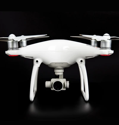

Aerospace & UAV
WJ Prototypes is your 3D manufacturing partner from prototype to large scale production.

Consumer Electronics
New Product Introduction Solutions for Consumer Electronics.

Robotics & Automation
Need some assistance bringing your robotic device or parts from the sketch-board to reality?

Medical Devices
The medical industry needs high quality, dependable and safe parts and products.

Automotive
New Product Introduction Solutions for Automotive

Industrial Machinery
The main purpose of industrial prototyping is to take the product from drawings into the real world.
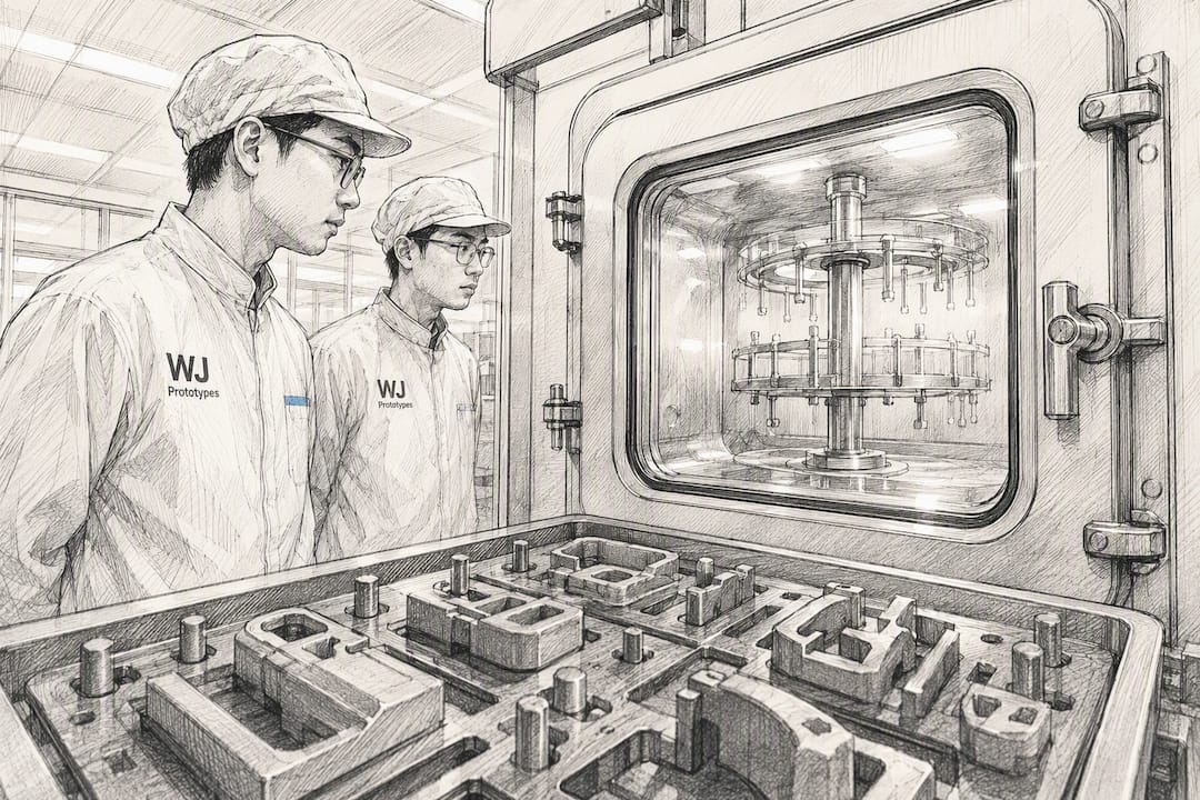
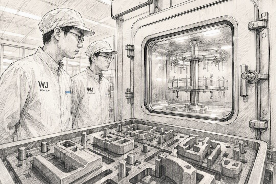
Automated vapor polishing produces optical-grade, glass-like surfaces on compatible thermoplastics when the recipe is right, cutting Ra from over 8 microns to under 0.8 microns while sealing the surface against moisture and stress. It beats hand-sanding on repeatability and cycle time for complex geometries, but it comes with real tradeoffs: material limits, a small but non-zero dimensional shift, and solvent-handling requirements that demand proper ventilation and recovery systems.
TL;DR:
- Vapor polishing is effective mainly on amorphous thermoplastics like ABS, polycarbonate, and PMMA, which reliably soften and reflow for optical clarity.
- Proper part design, including vents for enclosed cavities and consistent wall thickness, is crucial to prevent vapor pooling and surface deformation during processing.
- Automated systems achieve consistent surface finish, reducing Ra from over 8 microns to below 0.8 microns, with dimensional changes typically under 0.4 percent.
- Process parameters such as solvent choice, temperature, pressure, and exposure time must be carefully optimized through a sample matrix to ensure optical clarity without dimensional drift.
- In-house vapor polishing suits high-volume applications with traceability needs, but outsourcing remains cost-effective for low-volume or one-off prototypes.
Vapor polishing works by exposing a plastic part to a controlled solvent vapor that condenses on the surface, softens the outermost layer, and lets surface tension pull peaks and valleys into a smooth, continuous film. Think of it as a controlled, momentary melt: the polymer doesn't liquefy in bulk, but the top few microns flow just enough to erase print lines, tool marks, and sanding scratches. Once the vapor exposure stops, the surface reflows and hardens into a glassy skin.
That mechanism separates vapor polishing from two related but distinct techniques. Solvent dipping submerges the part directly in liquid solvent, which acts faster but is far harder to control and often leaves drip lines or uneven gloss. Manual buffing uses mechanical abrasion and polish compounds, which can achieve clarity on simple shapes but struggles with undercuts, ribs, and internal features a technician's hand can't reach evenly.
Choosing automated vapor polishing over the alternatives comes down to a few practical questions:
If you answered yes to two or more of those, automation is worth specifying. A one-off display prototype with a single smooth face might not justify the setup at all.
Not every polymer takes to vapor exposure the same way, and picking the wrong material is the single most common reason engineers get hazy or uneven results instead of optical clarity.
Amorphous thermoplastics respond best because their molecular structure allows uniform softening and reflow. Semi-crystalline polymers tend to resist evenly and can develop a mottled, frosted look instead of true gloss.
For SLA-printed clear parts specifically, resin selection and build orientation drive as-printed clarity before vapor polishing ever enters the picture. Stratasys Direct's finishing guide notes that resins like Watershed XC 11122 and WaterClear Ultra 10122 need orientation planning to minimize visible layer lines, since those lines telegraph through even after aggressive post-processing. When a resin part has heavy layer stepping or the color additive is unpredictable, a clear topcoat over sanded SLA often outperforms vapor polishing and involves less risk of the pooling and haze defects that show up later in this guide.
Industrial vapor polishing runs inside a sealed chamber, not an open tank, and that distinction is what makes automation possible at all. A typical automated cycle moves through four phases:
Systems built around this cycle, such as the AMT PostPro line, describe sealed-chamber conditioning specifically to reach recessed features and complex internal geometry that a technician with a rag and buffing wheel simply cannot access consistently. Industrial platforms like DyeMansion's Powerfuse S / VaporFuse system add closed-loop solvent circulation, PFAS-free fluids, and Industry 4.0 connectivity, which lets a facility log every cycle against a material ID for traceability.
The automation piece matters most in two places: recipe storage, so a technician isn't eyeballing exposure time, and monitoring, so a chamber fault stops the cycle instead of over-exposing a part. Reported results from these systems show Ra dropping from over 8 microns to below 0.8 microns, with the sealed surface also resisting moisture uptake, a real benefit for parts headed into humid test environments.
Pro Tip:Log every cycle's chamber temperature, vapor dose, and exposure time against the part's material lot number, even for prototypes. When a client asks you to reproduce a finish six months later, that log is the difference between a two-hour rerun and a two-week trial-and-error project.
Three variables decide whether a part comes out glass clear or subtly hazy: solvent choice, temperature and pressure, and exposure time. Get any one wrong and the others can't compensate.
Solvent selection starts with vapor pressure and solubility parameters that match your specific polymer. A solvent too aggressive for the material will over-soften the surface and blur fine features; one too mild won't reflow the surface at all. Safety profile matters just as much as chemistry: lower-flashpoint solvents demand tighter ATEX-rated controls, so many facilities weight solvent choice partly on what their ventilation and recovery infrastructure can safely handle.
Temperature and pressure work together to control how much of the vapor actually condenses on the part versus staying airborne. Higher chamber temperatures speed up softening but also increase the risk of over-exposure and the small dimensional creep that comes with it. Vendor data on dimensional change from industrial systems typically shows shrinkage or growth held typically under about 0.4 percent, translating to somewhere in the range of 20 to 40 microns on a typical prototype-sized feature. That's tight enough for most visual prototypes but worth flagging on anything with a mating tolerance under half a millimeter.
Exposure time is the lever most engineers reach for first, and it's the one that most directly trades gloss for dimensional stability. Longer exposure deepens the reflow and gloss but pushes the part further into that dimensional-change window. Shorter exposure protects tolerance but may leave micro-texture behind, especially on matte-finish 3D printed parts with heavier layer lines.
The only reliable way to lock in settings for a new material is a sample matrix, not a single test run. A practical approach:
That matrix approach costs a few hours of chamber time up front but saves far more in scrapped parts once you scale to a real order.
The single most common automated vapor polishing failure isn't a bad recipe, it's a part geometry that traps vapor in a low spot and holds it there until the surface over-softens, sags, or fully collapses. Solvent vapor behaves like a heavy gas inside a chamber: it settles into cavities, blind pockets, and downward-facing recesses, and unlike a liquid dip, there's no way to simply drain it out mid-cycle. Design the part wrong and you'll melt a feature you never intended to touch.
Follow these rules when you're designing anything headed for a vapor chamber:
Pro Tip:If a part has a cavity you cannot vent for functional reasons, orient it in the chamber so the opening faces upward during dosing. Vapor still settles into it, but an upward-facing opening lets more of it escape during the recovery phase than a downward-facing one ever will.
Scaling from a single prototype to a small batch adds one more variable: chamber loading. Parts placed too close together create localized vapor concentration between them, which is why a recipe validated on a single part sometimes produces uneven results at volume. Rerun your sample matrix at your actual batch density, not just on an isolated test coupon.
Hand-sanding wins on capital cost for a single one-off part and loses almost everywhere else once volume or repeatability enters the picture.
| Factor | Manual hand-sanding | Automated vapor polishing |
|---|---|---|
| Cost structure | Low capital, high labor per part | High capital (chamber, solvent recovery), low labor per part at volume |
| Dimensional accuracy | Operator-dependent, can vary part to part | Typically under 0.4% change, consistent across a batch |
| Surface result | Directional scratch patterns, gloss varies by hand pressure | Uniform gloss across all reachable surfaces, including internal features |
| Internal stress | No thermal input; risk is purely mechanical (micro-scratches) | Can heal surface micro-cracks, in some reported cases raising elongation-at-break by up to 200% |
| Cycle time | Scales linearly with part count and complexity | Fixed chamber cycle regardless of part count within a load |
| Best fit | Single prototypes, simple geometry, tight budgets | Complex geometry, repeat runs, optical-grade targets |
The internal stress line deserves a closer look because it cuts both ways. Vapor exposure can heal fine surface micro-cracks left over from printing or machining, which is part of why some vapor-polished parts test stronger than their as-printed counterparts. But a part carrying real residual thermal stress from an aggressive print or an uneven cooling cycle can respond to vapor exposure by developing new micro-cracking instead of healing existing ones. If a part has visible warping tendencies or was printed with a known thermal gradient, anneal it before vapor exposure rather than after. Combining CNC machining with 3D printed parts for stress relief on critical features ahead of finishing avoids this problem entirely.
Break-even between the two methods usually shows up somewhere between 10 and 30 parts per run, depending on geometry complexity, though a facility that already owns a chamber sees that threshold drop to nearly zero.
Optical clarity isn't a visual judgment call once you're shipping parts to a client; it needs measurable acceptance criteria and a repeatable test method.
The core metrics are surface roughness (Ra), haze or light transmission percentage, and gloss units measured at a standard angle, usually 60 degrees. ASTM maintains accepted test standards for polymer surface characterization that give engineers a defensible protocol to cite when a client questions a result.
Reported industrial Ra improvements run from over 8 microns down to under 0.8 microns, a tenfold reduction that's the practical threshold for a surface most people would call glass clear. When a part still shows minor haze after vapor exposure, a clear UV-stable topcoat can push transmission the rest of the way, though a topcoat adds its own cure time and slightly changes gloss uniformity, so treat it as a finishing step, not a substitute for a properly tuned vapor cycle. Details on combining surface finishes for layered results are worth reviewing before you commit to a coating step.
Automated doesn't mean unsupervised. Solvent vapor is flammable and often carries inhalation risk, and facility-level controls remain necessary even with a sealed chamber doing the work.
Closed-loop solvent recovery keeps most of the vapor out of the workroom air and reduces the volume of hazardous waste a facility has to manage, and vendor documentation for systems like AMT's platforms notes design alignment with ATEX and OSHA expectations through sealed enclosures and recovery loops. That alignment describes the equipment design, not a substitute for your own facility controls.
Waste solvent still needs proper collection and recycling rather than disposal down a drain, and spent filtration media counts as hazardous waste under most jurisdictions. Even a fully automated chamber needs ventilation monitoring near the loading door, where vapor escapes briefly during part loading and unloading, and operators should wear the PPE appropriate to the specific solvent in use, not a generic glove-and-goggles standard borrowed from another process.
Before committing a design to automated vapor polishing, run it against this list: material confirmed compatible (amorphous thermoplastic or clear resin), no unvented internal cavities, wall thickness consistent within the part, critical dimensions identified for masking, and residual stress addressed through annealing if the part was printed or machined aggressively.
For a new material, the 3x3 sample matrix from the parameters section above (low/medium/high exposure crossed with low/medium/high temperature) remains the fastest path to a validated recipe. Document gloss, haze, and one critical dimension per coupon.
WJ Prototypes' engineering team applies this same qualification approach across SLA, SLS, and MJF prototypes before committing a client's production geometry to a vapor cycle, drawing on material data across its 3D printing lineup to flag compatibility issues before a part ever reaches the chamber.
The honest answer depends on volume, not ambition. A team running dozens of optical prototypes a year rarely justifies the capital cost of a chamber with closed-loop recovery, ATEX-rated ventilation, and a trained operator. A team running that volume monthly probably does.
What matters more than owning the equipment is whether whoever runs it, in-house or a partner, offers recipe-based repeatability and traceable cycle logs tied to material lot numbers. That capability, common on industrial platforms with closed-loop solvent recovery, is what separates a one-off lucky result from a process you can rerun with confidence. Validate any new material or geometry with a sample run and hard acceptance numbers before trusting it on a client deliverable.
— Nas
Some providers offer a faster path to an optical-grade prototype than building an in-house vapor chamber or relying on hand-sanded finishes by matching material, print process, and finishing method before committing to a production run.
When you request a vapor-polished or optically clear prototype, include the target material, your acceptance criteria for Ra and haze, and any critical dimensions that can't drift during finishing. That upfront detail lets the team flag pooling risks or dimensional concerns before the part ever reaches a chamber, rather than after a batch comes out hazy. If your geometry needs tight tolerances restored after finishing, WJ Prototypes' CNC machining services can bring critical features back into spec without a second full production run. Start with an instant quote to spec a specimen run and see how your design performs before locking in volume.
Yes, provided the material is amorphous and compatible; SLS and MJF nylon parts respond less predictably than SLA resins or machined ABS and polycarbonate due to surface porosity.
Hand-sanding has lower upfront cost per part but higher labor cost at volume; automated systems carry higher capital cost but typically break even against manual finishing somewhere between 10 and 30 parts per run.
It can smooth minor layer lines on compatible materials, but heavy stepping from coarse print settings usually needs sanding first, since vapor exposure alone won't remove deep ridges.
Pooled vapor over-softens the trapped surface, which can cause sagging, warping, or full collapse of thin internal walls, which is why every enclosed cavity needs a drain or vent path before processing.
Vapor polishing is used in those sectors, but traceability matters more than in general prototyping. Closed-loop systems that log cycles against material IDs give the process record those industries typically require.
Master Precision Part Fabrication Process for High Quality Parts
Precision Engineering in Prototyping: Driving Breakthroughs
Metal Fabrication Step by Step for Precision Prototyping
Precision Engineering Methods: Your Step-by-step Guide
SERVICES
RESOURCES