



- Room 1807, Unit 9, Building 2, Shangxing Commercial Street, Shangde Road, Shangxing Community, Xinqiao Subdistrict, Bao'an District, Shenzhen City, China
CONTACT US

WhatsApp


Contact Us
Our team is on stand by, waiting toassist you.

Videos
A large collection of educational videos and tutorials.

About Us
Learn about our company, leadership, and mission totransform manufacturing.

Privacy Policy
Applies to all personal information collected through and/or processed in connection.
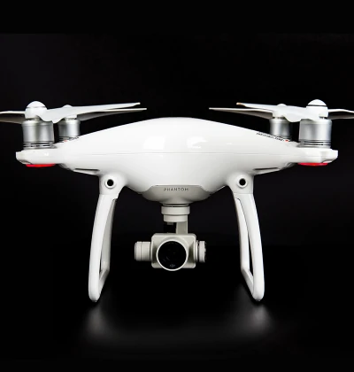

Aerospace & UAV
WJ Prototypes is your 3D manufacturing partner from prototype to large scale production.

Consumer Electronics
New Product Introduction Solutions for Consumer Electronics.

Robotics & Automation
Need some assistance bringing your robotic device or parts from the sketch-board to reality?

Medical Devices
The medical industry needs high quality, dependable and safe parts and products.

Automotive
New Product Introduction Solutions for Automotive

Industrial Machinery
The main purpose of industrial prototyping is to take the product from drawings into the real world.

TL;DR:
- Precision engineering in prototyping emphasizes designing processes that verify compliance at every stage, not just achieving tight tolerances on paper. Small errors in machining can propagate, leading to costly rework, field failures, and regulatory issues, especially in regulated industries like aerospace and medical devices. Effective verification with calibrated equipment, traceable documentation, and advanced measurement techniques ensures the integrity and acceptance of high-precision parts.
Imagine a spinal implant prototype reaches final inspection and fails because a bore is off by four microns. The surgeon’s team is waiting. The regulatory window is closing. The rework cost will be six figures. This scenario plays out more often than the industry admits, and it almost always traces back to a gap between machining intent and verified reality. Precision engineering in prototyping is not just about achieving tight tolerances on paper. It is about designing a process that delivers proof of compliance at every stage, from raw stock to final inspection report.
| Point | Details |
|---|---|
| Micro-level tolerances matter | High-precision prototyping demands tolerances down to millionths of an inch for success in advanced industries. |
| Preparation drives results | Proper matching of specialized tools and materials is the foundation for effective precision methods. |
| Step-by-step accuracy | Structured process—from design through verification—minimizes errors and ensures repeatable results. |
| Verification is non-negotiable | Rigorous measurement, calibration, and uncertainty control secure both compliance and client trust. |
| Documentation wins business | Proving your parts’ accuracy matters more to clients than theoretical machining perfection. |
In aerospace, automotive, medical, and robotics applications, a single out-of-tolerance feature does not stay isolated. It propagates. A bearing bore that is two microns oversized creates clearance that amplifies vibration. That vibration degrades sensor accuracy. Degraded sensor accuracy triggers false fault codes. Suddenly, a dimensioning oversight from week two of the program is grounding an aircraft or pausing a surgical robot’s FDA submission.
The economic consequences compound quickly. Rework on a complex titanium component can cost three to five times the original machining cost. Field failures in regulated industries add liability, recall costs, and reputational damage that no schedule can absorb. This is why precision machining accuracy is treated as a first-principles requirement, not a finishing touch.
The tolerance benchmarks in these sectors push well beyond everyday manufacturing. Honing and lapping can achieve tolerances measured in millionths of an inch, far surpassing the precision of most other machining methods by one or two orders of magnitude. That level of control requires deliberate process design, not just expensive equipment.
Key risks that engineers and procurement managers must actively manage:
Pro Tip: Build your inspection plan during design, not after machining. Knowing which features require CMM verification lets you design fixturing and datum schemes that support repeatable measurement setups from day one.
Now that the stakes are clear, let’s break down what you’ll need before starting.
Successful precision engineering starts with matching your process stack to the application requirements before a single line of G-code is written. Getting this wrong at the preparation stage is the most expensive mistake teams make, because it surfaces at the worst possible moment: final inspection.
Core equipment categories for precision prototyping and low-volume production:
| Equipment | Primary function | Achievable accuracy |
|---|---|---|
| 5-axis CNC machining center | Complex geometry, tight positional tolerances | ±0.005 mm typical |
| Wire and sinker EDM | Hard materials, no cutting force, blind cavities | ±0.002 mm typical |
| Surface and cylindrical grinders | Flat and round form accuracy | Sub-micron with dressing |
| CMM (coordinate measuring machine) | Dimensional verification, GD&T reporting | ±0.001 mm or better |
| Honing and lapping machines | Final bore and flat surface finishing | Millionths of an inch |
Honing and lapping refine drilled or bored surfaces for extremely tight tolerances in precision engineering manufacturing, making them indispensable for hydraulic actuator bores, medical implant surfaces, and fuel system components. These are not optional finishing steps for high-spec parts. They are the process.
Material selection is equally critical. Explore precision part fabrication tools and the matching material requirements for each:
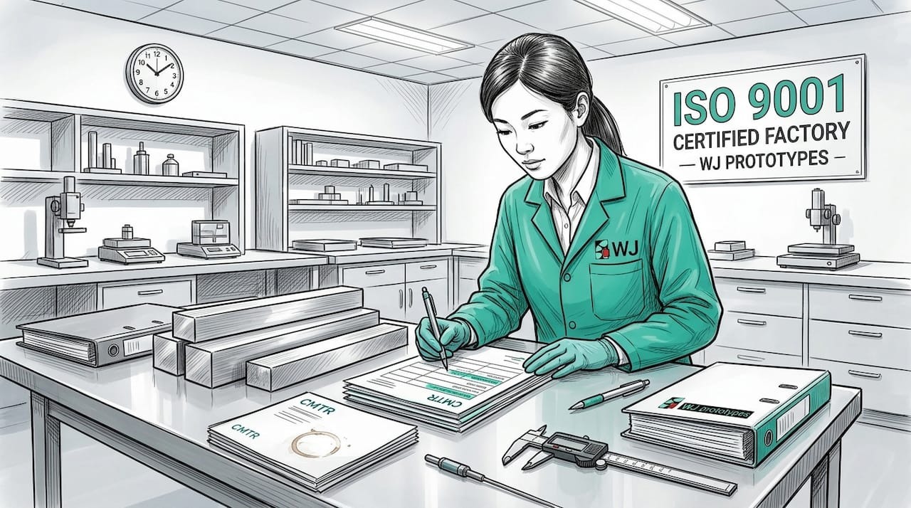
Pro Tip: Always request certified material test reports (MTRs) from your supplier before machining begins. Material composition deviations can shift machinability, surface finish behavior, and dimensional stability enough to invalidate your process plan.
One more consideration: environmental controls. Thermal expansion in a 20-meter CNC machine can move a feature by several microns per degree Celsius of ambient change. Shops doing sub-five-micron work maintain temperature control to within ±1°C. If your supplier cannot demonstrate environmental control, their stated tolerances are aspirational, not guaranteed.
With requirements in hand, you’re ready to start the methodical process of precision manufacturing.
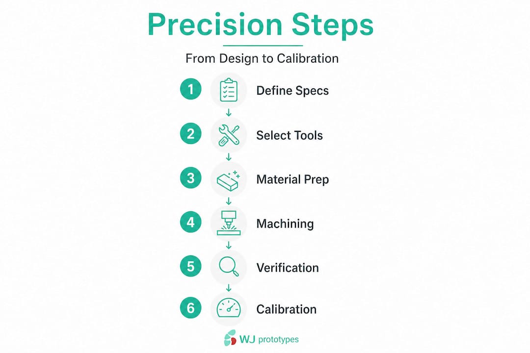
Here is the sequence that consistent, high-precision results depend on. Each step has a specific purpose and a specific failure mode if skipped or rushed.
Design for manufacturability (DFM) review. Before fixturing, validate that every tolerance on the drawing is achievable with available equipment. Flag GD&T callouts that require specific inspection setups. Identify which features drive cycle time and which drive risk. A DFM pass that catches one impossible callout saves days of rework.
Datum and fixturing design. Select primary, secondary, and tertiary datums that are stable, measurable, and match the CMM setup you’ll use for inspection. Fixturing that does not support the part at the right contact points introduces clamping-induced distortion that no amount of skilled machining can overcome.
Rough machining (stock removal). Remove the bulk of material while maintaining generous leave-stock (typically 0.3 to 0.5 mm on critical surfaces). The goal here is speed and thermal management, not precision. Aggressive roughing generates heat and stress. Allow parts to stabilize thermally before moving to semi-finish.
Stress relief (where required). For tight-tolerance aluminum and titanium components, a thermal stress relief cycle between rough and finish machining prevents post-machining distortion. This step is often skipped under schedule pressure and almost always regretted.
Semi-finish and finish machining. Use reduced depths of cut, fresh tooling, and slower feeds to achieve final geometry. Monitor spindle load and surface finish in real time. For critical bores, leave 0.01 to 0.02 mm for honing.
Post-process finishing (honing, lapping, grinding). Achieve final surface finish and form accuracy. Multi-sensor fusion and adaptive compensation allow for nanometer-scale setup accuracy in advanced machine tools, meaning modern precision centers can self-correct tool wear and thermal drift mid-cycle when equipped with the right sensor architecture. This is the technology gap between a capable shop and a precision shop.
In-process gauging. Use air gauges, bore gauges, or probing cycles to check critical features before the part leaves the machine. Catching a dimension at this stage costs minutes. Catching it at final CMM costs hours and possibly a recut.
Final CMM inspection. Execute the full inspection plan against the approved drawing. Generate a first article inspection (FAI) report with actual measurements, nominal values, and deviation for every controlled dimension.
Traditional vs. sensor-fusion precision workflows:
| Workflow element | Traditional approach | Sensor-fusion approach |
|---|---|---|
| Thermal compensation | Manual offsets at setup | Real-time adaptive correction |
| Tool wear detection | Scheduled replacement | Acoustic/force sensor monitoring |
| Setup accuracy | Operator skill dependent | Automated nanometer-scale probing |
| Dimensional feedback | Post-process CMM only | In-process and post-process combined |
| Reject rate (typical) | 2-5% for tight-tolerance parts | Below 0.5% with full integration |
Review the CNC precision success framework to understand how these workflow elements translate into practical machine center setup and programming decisions.
Execution is critical, but without calibration and verification, even the best work can fail delivery.
Machining a perfect part and proving it is a perfect part are two different disciplines. The verification stage is where projects are won or lost at acceptance, and where procurement managers earn or lose confidence in a supplier.
The global standard for CMM performance in precision manufacturing is ISO 10360. Modern CMM practice increasingly relies on uncertainty-aware verification against international performance standards, including volumetric length error (E) and probing-related errors (P). These two parameters together define whether a CMM’s measurement output is trustworthy for the tolerance band you are working within.
“You cannot manage what you cannot measure, and you cannot trust a measurement you have not verified.” This is the governing principle behind ISO 10360 and every credible precision inspection program.
Here is a structured verification process for high-precision parts:
CMM calibration check. Verify the CMM against a calibrated reference artifact before each inspection session. Document the calibration results. If the CMM’s stated uncertainty is within 1/4 of the tightest part tolerance, proceed. If not, the CMM is not fit for the inspection task.
Fixture and datum alignment. Align the part to its primary, secondary, and tertiary datums in the CMM software. Misalignment at this step is one of the most common sources of false rejections and false acceptances in precision inspection.
Execute volumetric length error (E) test. Measure calibrated length standards at multiple orientations in the CMM’s working volume. This quantifies the machine’s ability to report true distances in three dimensions, not just along a single axis.
Execute probing error (P) test. Using a certified reference sphere, measure from multiple approach directions. Probing errors reveal stylus qualification problems and probe head issues that corrupt form measurements.
Part measurement and uncertainty estimation. Measure all controlled features. Report the result as a value plus its measurement uncertainty (for example, 24.998 ±0.002 mm). A result without uncertainty is incomplete for precision procurement acceptance.
Generate and archive the inspection report. Include drawing revision, equipment IDs, calibration status, temperature at time of inspection, and operator identification. Procurement teams in regulated industries require this for lot acceptance and regulatory submissions.
Follow CMM calibration steps to build a repeatable calibration workflow that satisfies both internal quality gates and customer requirements.
Pro Tip: If a feature is borderline, measure it at least three times and report the mean and range. A single measurement on a tight-tolerance feature is not statistically defensible in an acceptance dispute.
Review the quality control CNC and precision verification in prototyping resources to align your inspection process with industry-accepted documentation standards before your next FAI submission.
After verification, let’s consider overlooked truths and expert perspective on deploying these methods for real-world success.
Here is the uncomfortable reality that most machining-focused content avoids: a part that is dimensionally perfect but has no documented proof of measurement is commercially worthless in regulated industries. The customer cannot accept it. The regulator cannot approve it. The procurement manager cannot sign off on it.
We see this pattern regularly. A supplier invests in high-end five-axis equipment and delivers parts that are, by every physical measure, exceptional. But their inspection reports are incomplete. Measurement uncertainty is not quantified. Calibration records are missing. The customer’s quality team rejects the lot, not because the parts are bad but because they cannot be proven to be good.
The winning position in precision manufacturing is not the shop with the most expensive machine tool. It is the shop that can demonstrate compliance with evidence that withstands scrutiny. That means trained metrologists, calibrated equipment, traceable reference standards, and inspection documentation that matches what the customer’s acceptance protocol actually requires.
This also shifts where you should invest attention when choosing precision methods for a new program. Before asking “what machine can hold this tolerance?”, ask “how will we prove we held this tolerance?” If you cannot answer the second question, the first one does not matter.
The verification infrastructure, CMM time, metrology software, calibration cycles, and trained inspection staff, often costs as much to operate as the machining equipment itself. That investment is not overhead. It is the product. It is what you are selling when a customer buys precision parts from you.
As you prepare to execute or source your next demanding prototype or low-volume production run, access to the right combination of machining capability and verification rigor is what separates fast delivery from failed inspection. WJ Prototypes brings both to every engagement. From CNC machining materials selection guidance to full first article inspection support, our team works alongside your engineers to match process methods to tolerance requirements from day one. Our CNC machining in China capabilities span five-axis milling, EDM, grinding, and honing, all supported by ISO-certified measurement and inspection workflows. Use our instant quoting system through our rapid prototyping services platform to get a fast, accurate cost picture for your next project.
Advanced honing and lapping methods can routinely reach tolerances measured in millionths of an inch, especially in aerospace and medical applications where bore geometry and surface finish are both controlled.
CMM verification follows ISO 10360 standards and includes systematic E and P tests, with measured results compared against manufacturer tolerance limits and calculated measurement uncertainty before acceptance decisions are made.
Multi-sensor fusion with adaptive compensation, including acoustic emission, cutting force, and environmental sensors integrated with real-time control algorithms, provides nanometer-scale setup accuracy in modern precision machine tools.
Aluminum 7075, titanium Ti-6Al-4V, high-grade tool steels, PEEK, and Ultem are the most common choices, selected for their machinability, dimensional stability under temperature variation, and ability to hold fine surface finishes across repeated operations.
Measurement uncertainty defines the statistical confidence boundary of your inspection result. Without quantifying it, you cannot determine whether a borderline dimension is truly in tolerance or truly out, making the ISO 10360 uncertainty framework essential for credible acceptance decisions in regulated industries.
SERVICES
RESOURCES