



- Room 1807, Unit 9, Building 2, Shangxing Commercial Street, Shangde Road, Shangxing Community, Xinqiao Subdistrict, Bao'an District, Shenzhen City, China
CONTACT US

WhatsApp


Contact Us
Our team is on stand by, waiting toassist you.

Videos
A large collection of educational videos and tutorials.

About Us
Learn about our company, leadership, and mission totransform manufacturing.

Privacy Policy
Applies to all personal information collected through and/or processed in connection.


Aerospace & UAV
WJ Prototypes is your 3D manufacturing partner from prototype to large scale production.

Consumer Electronics
New Product Introduction Solutions for Consumer Electronics.

Robotics & Automation
Need some assistance bringing your robotic device or parts from the sketch-board to reality?

Medical Devices
The medical industry needs high quality, dependable and safe parts and products.

Automotive
New Product Introduction Solutions for Automotive

Industrial Machinery
The main purpose of industrial prototyping is to take the product from drawings into the real world.
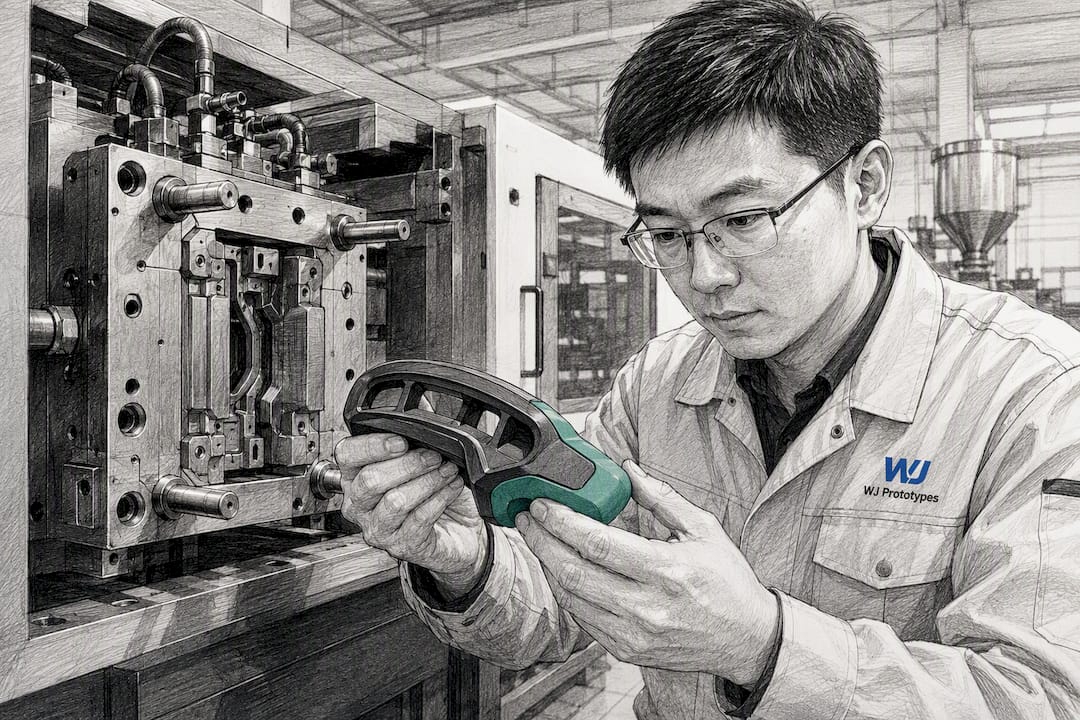
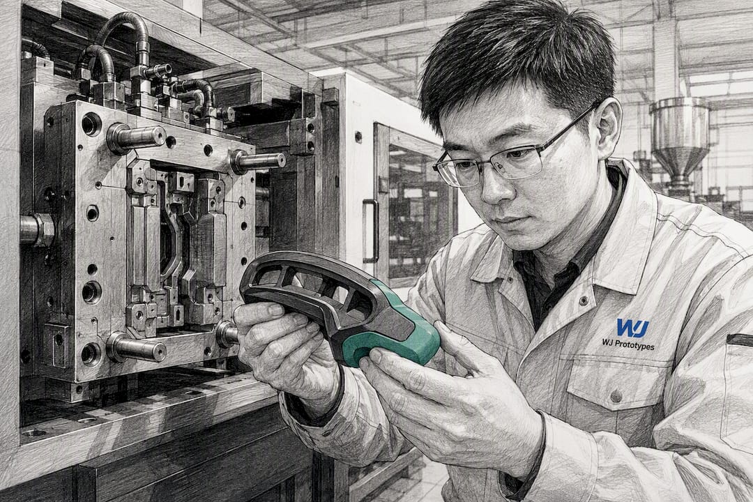
For most prototype-to-production programs, start with insert overmolding on an aluminum trial tool to validate adhesion and ergonomics fast, then commit to two-shot molding once annual volume justifies dedicated tooling, or move to co-injection when the part needs a genuinely layered internal structure. Material compatibility, not tooling budget, decides whether any of it holds together.
TL;DR:
- Material compatibility and proper process control are critical; testing adhesion with peel strength measurements before committing to production tooling minimizes failures.
- Insert overmolding is suitable for prototype and low-volume runs due to its low tooling complexity, while two-shot molding is justified at higher volumes by its faster cycle times and automation.
- Bonding success depends heavily on selecting the right TPE for each substrate and maintaining specific processing parameters like residence time and surface cleanliness.
- Mechanical interlocks such as undercuts, dovetails, and through-holes enhance adhesion and durability, especially in applications with impact or thermal cycling.
- Rapid prototyping with aluminum trial tools ensures early detection of material pairing or design issues, saving costs and preventing delays in full-scale production.
Overmolding bonds a second material, usually a soft elastomer, onto or around a rigid substrate to create one finished part with two distinct textures or functions. Co-injection does something different: it injects two resins into the same cavity in a single cycle, producing a layered structure where one material forms a skin and the other fills the core. Both fall under the umbrella of multi-material manufacturing, but they solve different engineering problems and get chosen for different reasons.
The industry-standard term you will see in supplier RFQs and process documentation is "two-shot" or "multi-shot molding" for the injection method, and "insert molding" for the simpler cousin that uses a pre-formed part dropped into a second cavity. Overmolding is the umbrella concept; insert molding and two-shot molding are the two dominant ways to execute it. Co-injection is a distinct process family that happens to get lumped into the same conversations because it also produces multi-material parts, even though the mechanics are closer to sandwich molding than to overmolding at all.
Getting this right in a Chinese manufacturing environment means understanding not just the chemistry, but which process a given factory floor is actually set up to run well, and how to test adhesion before you commit six figures to hardened production tooling.
Insert overmolding takes a substrate part, often injection molded separately or even metal, and places it into a second mold cavity where a compatible material is shot over or around it. It typically runs on a standard single-shot machine with a rotating or shuttle fixture, which keeps tooling costs low and machine availability high across almost any qualified Chinese molder.
Two-shot (multi-shot) molding uses a specialized machine with two or more injection units feeding a single mold that rotates or transfers the part between cavities within one cycle. Both materials get molded in a continuous automated sequence, no manual handling between shots. That automation is exactly what makes it worth the higher tooling investment once volume climbs.
Co-injection injects a skin material first, followed immediately by a core material through the same nozzle and gate, creating a true layered cross-section rather than two adjacent zones. According to the Moldflow overmolding guide, co-injection is chosen specifically for unique part behavior, like a soft-touch skin over a structural or recycled core, despite carrying the highest tooling and process complexity of the three methods.
Here's how the tradeoffs actually shake out on a factory floor:
The practical decision rule is simple. Prototype and low-volume runs almost always start with insert molding because you can validate the design on a standard machine with minimal upfront cost. Plan for two-shot once you know the geometry is stable and volume justifies dedicated tooling. Reach for co-injection only when the part genuinely needs a hidden internal material transition that insert molding or two-shot cannot replicate.
Adhesion happens two ways: chemical bonding, where the overmold material actually cross-links or fuses at the molecular level with the substrate, and mechanical locking, where geometry alone holds the two pieces together regardless of chemistry. The strongest parts use both, but chemical bonding is what determines whether you even need to design elaborate interlocks in the first place.
Thermoplastic elastomers vary enormously in what they will bond to, and picking the wrong TPE family for a given substrate is the single most common reason overmolding trials fail in early prototyping. Avient's TPE overmold design guide lists specific product families, including Dynaflex, Versaflex, and Versalloy, and notes that bonding behavior differs sharply between substrates like polypropylene, polycarbonate, and nylon. A TPE formulated to bond well to PP will often fail outright on PC unless it's a different grade entirely.
Some pairings are close to plug-and-play. Styrenic TPEs generally bond well to PP and ABS without any surface treatment. Others are genuinely risky: bonding a soft TPE reliably to nylon or PC frequently requires either a specially formulated grade or a tie layer, and skipping that step is how teams end up with a peel-test failure three weeks into tooling.
Pro Tip:Never assume a TPE that worked on one substrate in a past project will work the same way on a new one. Pull the specific datasheet for the exact resin grade and check the compatibility chart before you cut steel, not after.
Processing conditions matter almost as much as the material pair itself. Avient recommends keeping TPE residence time under roughly 4 to 5 minutes for GLS formulations, since extended dwell time in the barrel degrades the material and weakens the bond it forms on contact with the substrate. Melt temperature, pigmentation load, and moisture in either resin all shift adhesion strength in ways that are invisible until you pull a peel test.
A short list of processing variables that quietly wreck adhesion:
The single most reliable move here is treating the supplier datasheet as the primary decision reference rather than anecdotal "this combo worked for us once" advice passed between engineering teams.
Chemistry gets you most of the way there, but mechanical interlocks are the insurance policy for every part that will see impact, thermal cycling, or repeated flexing in the field. Good design pairs the right resin with geometry that would still hold the part together even if the bond were weaker than expected.
Wall thickness rules matter more here than in single-material parts. Thin overmold sections, generally anything under about 0.5mm, tend to freeze off before they fully fill and pack against the substrate, leaving weak, porous bond lines. Keep minimum overmold wall thickness closer to 0.8 to 1.2mm wherever ergonomics allow, and taper transitions gradually rather than stepping them abruptly.
Shutoff placement, where the mold steel meets the substrate edge to prevent flash, needs to sit on a flat, well-supported plane rather than a curved or thin section, or you'll fight flash for the life of the tool. Vents belong at the last-fill point of the elastomer flow path, almost always the point farthest from the gate, and should be sized generously since TPEs vent gas differently than rigid engineering plastics.
Before sending a design out for supplier RFQs, run it against this checklist:
The machine you specify matters as much as the design itself. Reciprocating general-purpose machines fitted with a rotary or shuttle table can run insert overmolding at low to moderate volumes without any special investment, and most qualified Chinese injection molding factories already have several on the floor. True multi-shot machines, with two or more independently controlled injection units synced to an index or core-back mechanism, are a different category entirely and not every shop owns one.
A rough clamp tonnage rule of thumb: figure roughly 3 to 5 tons of clamping force per square inch of projected part area for the rigid substrate shot, and adjust upward if the overmold geometry adds significant projected area of its own. Undersized clamp tonnage on the second shot is a common, avoidable cause of flash on two-shot parts.
Shot sizing on the TPE side deserves particular attention. Smaller TPE shot units reduce the material's residence time in the barrel between cycles, directly protecting bond strength on parts that run at slower cycle rates. Avient suggests starting nozzle diameters between roughly 1/16 inch and 3/16 inch for better shear heating and less cold-slug carryover into the cavity, a detail that rarely makes it into a standard tooling spec sheet but has an outsized effect on first-shot rejects.
Tool construction choices carry their own tradeoffs:
Committing to hardened production tooling before you've physically handled a part is how ergonomics problems and adhesion failures make it all the way to a production floor. The fix is a rapid-test workflow that validates both before that commitment happens.
The typical sequence for overmolding projects starts with a prototype substrate, often CNC machined or 3D printed in a representative material, then moves to a soft or aluminum trial tool for the actual overmold shot. Aluminum tooling cuts turnaround dramatically compared to hardened steel and still produces parts accurate enough for real peel testing and hands-on ergonomic evaluation. From there, run overmold trials across a small batch, pull peel-strength and adhesion-after-thermal-cycling data, score user ergonomics with actual test subjects holding the part, and check cycle-to-cycle consistency before iterating the design.
What to actually measure and report at each round:
This mirrors the same logic behind transitioning from low-volume vacuum casting to injection molding, where running small-batch tool trials before production tooling reduces handoff failures between prototype and production teams. WJ Prototypes runs this process under ISO-certified quality controls with documented process windows and controlled data transfer between prototyping and production-scale injection molding, so the parameters validated in a trial actually carry forward instead of getting re-derived from scratch on the production floor.
Pro Tip:Ask for the peel-test data from the trial tool in writing before approving production tooling. A verbal "it looked fine" from a supplier is not a spec, and it will not hold up if adhesion fails six months into a production run.
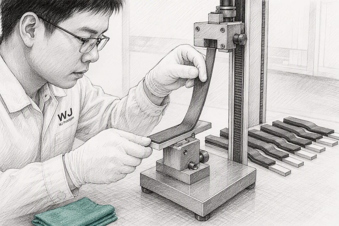
The volume math is what actually decides which process wins, more than any preference for one method over another. Insert molding stays economical up to roughly 20,000 to 50,000 units annually, since it avoids the cost of specialized rotary or two-shot tooling. Somewhere past that range, usually between 50,000 and 100,000 units depending on part complexity, the labor savings and cycle-time advantage of two-shot tooling starts paying back its higher upfront cost. Co-injection tooling generally only makes economic sense when the layered structure is a functional requirement, not a nice-to-have, since its complexity premium doesn't shrink much with volume.
Lead times vary by tooling category. Trial or soft tooling, aluminum or similar, commonly turns around in a couple of weeks in a well-equipped Chinese facility. Hardened production tooling for two-shot or co-injection molds typically runs several weeks longer given the added machining precision the shutoffs demand. Build ramp schedules with a pilot run of a few thousand units before committing to a full production release, giving quality teams time to catch drift that a small trial batch wouldn't reveal.
Quality control items worth locking into a trial acceptance agreement before tooling starts:
When a trial part comes back with a problem, the fix usually falls into one of a few known buckets rather than requiring a redesign from scratch.
Before issuing an RFQ, ask suppliers to commit to a documented list: sample test protocols, confirmed process windows for both shots, inspection metrics tied to your specific interlock and adhesion requirements, and full documentation of the resin grades used in trial versus what they propose for production. The decision rule that saves the most rework: change geometry when the failure is mechanical (interlock shape, wall thickness, shutoff placement), and tune process only when geometry is already confirmed sound and the failure is clearly adhesion or fill related.
Most teams treat material selection as a formality and geometry as the real engineering problem. It's backwards. A perfect dovetail interlock cannot rescue a TPE that was never formulated to bond with the substrate underneath it, but a well-chosen chemical pair often needs almost no mechanical help at all.
The bigger blind spot is communication with suppliers in China. Process windows discussed verbally during a factory visit rarely survive translation into the actual production run three months later. Get melt temperature, residence time, and clamp tonnage documented in writing during the trial, not summarized after the fact.
If there's one action worth taking before anything else: run the rapid overmold adhesion test on real trial tooling and get the peel-strength numbers in writing before you approve a single dollar of production steel.
— Nas
Running an adhesion and ergonomics test in China without an aluminum trial tool means finding out about a bad material pair after you've already paid for hardened steel. Rapid trial tooling can catch material pairing failures early by running insert overmolding trials, two-shot feasibility checks, and low-volume injection molding under ISO-certified process controls, helping ensure data from prototypes transfer cleanly into production.
Starting a program is straightforward. Send over your CAD model, flag the critical bonding surfaces and interlock geometry, state your target annual volume, and specify the acceptance tests you need passed, peel strength, thermal cycling, ergonomic review, whatever matters for your part. That's enough for a working quote and a realistic trial-tooling timeline. Get a rapid quote for your overmolding project and find out what a trial tool would look like for your specific material pair before committing to production steel.
Avient's TPE overmold design guide remains the most detailed public reference for matching specific TPE families to substrates and setting starting process parameters. The Moldflow overmolding guide covers the broader process concepts behind insert molding, two-shot, and co-injection in more technical depth. For a real-world look at how prototype-to-production handoffs work in practice, WJ Prototypes' writeup on moving from vacuum casting to injection molding and its guide to finding reliable molding factories in China both cover ground this article only touches on.
Overmolding bonds a second material onto or around a rigid substrate in a separate shot or step, while co-injection injects two resins into one cavity in a single cycle to create a true layered structure.
Move to two-shot molding once annual volume becomes high enough that the automation and cycle-time savings offset the higher tooling cost.
Bonding behavior varies by resin family and substrate, so check the specific supplier datasheet, such as Avient's TPE overmold design guide, rather than assuming a grade that worked on one substrate will bond equally well on another.
Avient recommends keeping residence time under roughly 4 to 5 minutes for GLS formulations, since longer dwell times degrade the material and weaken adhesion.
WJ Prototypes runs overmold trials on aluminum or soft trial tooling, then measures peel strength, thermal-cycling adhesion, and user ergonomics under ISO-certified process controls before recommending production tooling.
Material Selection in Prototyping from China | Key Material Choices
What Is Overmolding? A Guide for Product Designers
Role of Materials in Prototyping | Sourcing Quality Materials from China
Injection Molding Guide: Achieve Accurate Prototypes Fast
SERVICES
RESOURCES