



- Room 1807, Unit 9, Building 2, Shangxing Commercial Street, Shangde Road, Shangxing Community, Xinqiao Subdistrict, Bao'an District, Shenzhen City, China
CONTACT US

WhatsApp


Contact Us
Our team is on stand by, waiting toassist you.

Videos
A large collection of educational videos and tutorials.

About Us
Learn about our company, leadership, and mission totransform manufacturing.

Privacy Policy
Applies to all personal information collected through and/or processed in connection.


Aerospace & UAV
WJ Prototypes is your 3D manufacturing partner from prototype to large scale production.

Consumer Electronics
New Product Introduction Solutions for Consumer Electronics.

Robotics & Automation
Need some assistance bringing your robotic device or parts from the sketch-board to reality?

Medical Devices
The medical industry needs high quality, dependable and safe parts and products.

Automotive
New Product Introduction Solutions for Automotive

Industrial Machinery
The main purpose of industrial prototyping is to take the product from drawings into the real world.
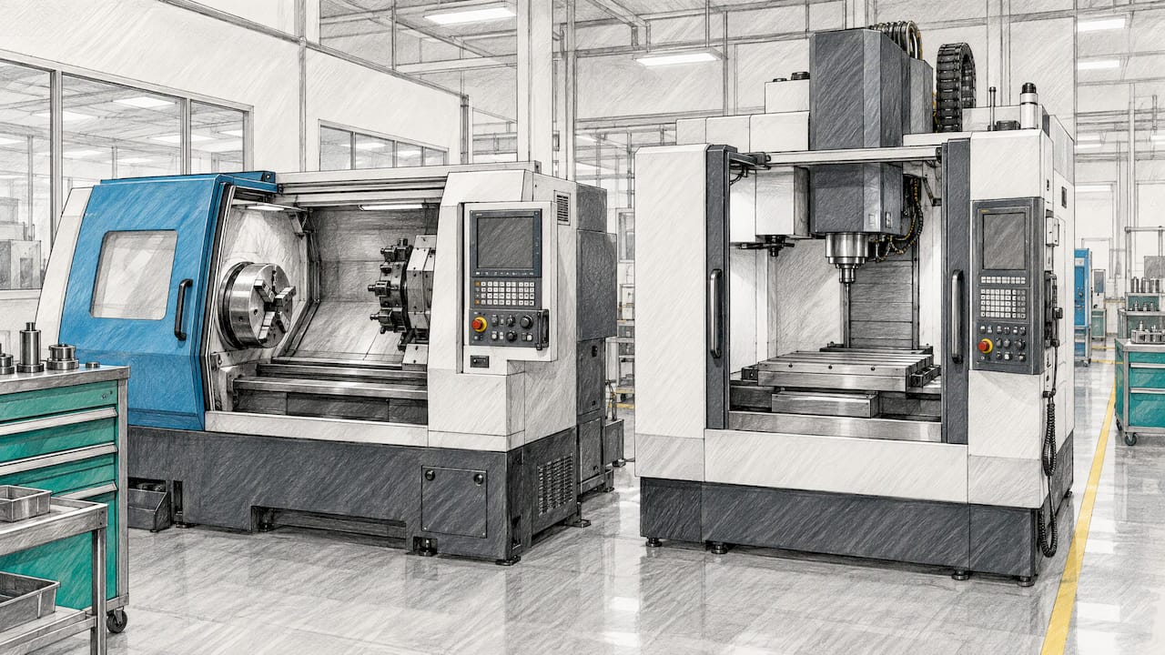
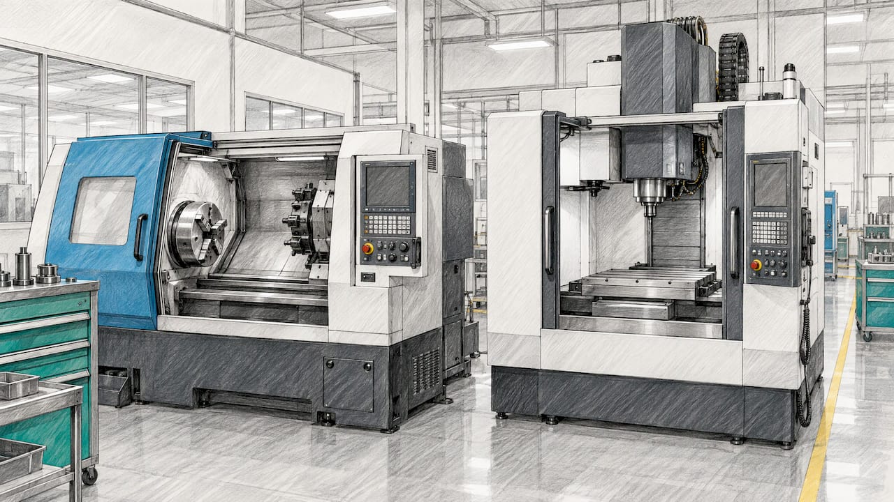
In CNC turning, the workpiece rotates while a cutting tool shapes it. In CNC milling, a rotating cutting tool removes material from a workpiece that is held still. That is the whole difference in one line, and it is the same difference you are asking about when you compare a lathe with a mill. Round parts usually go to turning. Flat, prismatic or contoured parts usually go to milling. Parts that are both go to a mill-turn setup or a two-step process.
This guide goes past the definition. It shows how to read your drawing, which features push a part toward one machine, how setup and configuration affect cost, and how to decide when you are buying prototypes or low-volume runs.
A lathe spins the part while the cutter stays put. George Washington University’s machine shop guide explains that a lathe typically uses a single-point cutter, and that the part can be held in collets, three-, four- or six-jaw chucks, between centers, on mandrels or on faceplates. Its primary use is round parts or round features.
A mill works the other way around. The same GWU guide describes a mill with an X-Y table and a Z-axis head, so the workpiece is clamped to the table while a rotating cutter moves into it. Erie Institute of Technology puts it the same way: in milling, a rotating cutting tool removes material from a secured workpiece, and in turning, the workpiece rotates while a cutting tool shapes it.
The “CNC” part simply means a computer drives the axes from a program, so the same toolpath repeats exactly from the first part to the fiftieth. If you run machines in-house, keeping them available matters as much as the process choice, and a preventive maintenance planning guide can help you schedule that work around production.

On a mill, axis count is the headline spec. Erie IT notes that a 3-axis mill moves along X, Y and Z, while 5-axis machines add rotational movement so machinists can produce complex surfaces with fewer setups. Fewer setups usually means fewer chances for error between operations.
On a lathe, the picture is different. A basic CNC lathe is built primarily for turning. A turning center may add live tooling and extra axis control, which lets it mill or drill in the same setup, again according to Erie IT.
Start with the shape. Autodesk’s Fusion guide says turning suits cylindrical or round components such as shafts, bolts, bushings and bearings, plus conical features and threaded surfaces. Milling suits flat and prismatic parts, complex contours, pockets and angled surfaces.
Erie IT lists the features in more detail. Turning produces outside and inside diameters, tapers, grooves and threads. Milling is especially useful for flat surfaces, slots, pockets, angled faces and complex contours.
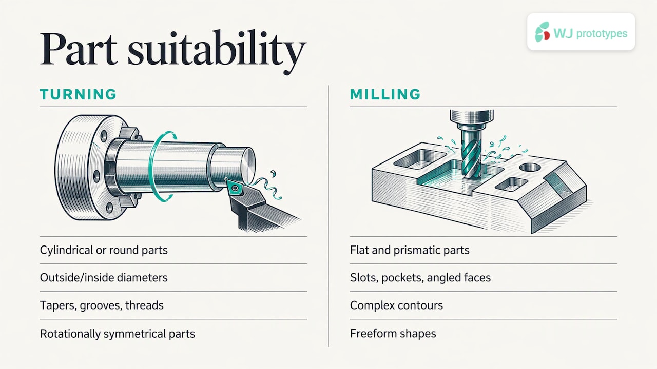
Keller Feinwerktechnik adds that 3- to 5-axis milling suits complex geometries, flat surfaces, pockets and freeform shapes, and that turning suits rotationally symmetrical parts and can add cross and drilling operations through driven tools.
| Feature or part | Turning | Milling | Mill-turn |
|---|---|---|---|
| Shaft, pin, bushing | Best fit | Possible, rarely efficient | Good if it also needs flats or cross holes |
| Threads, grooves, tapers on a round part | Best fit | Possible with special tooling | Good |
| Flat faces, slots, pockets | Not suited | Best fit | Good |
| Angled faces, contoured surfaces | Not suited | Best fit | Good |
| Enclosure, bracket, plate | Not suited | Best fit | Rarely needed |
| Round body with milled flats and cross holes | Needs a second operation | Needs a second operation | Best fit |
The table is a first-pass guide, not a law. Autodesk’s own rule of thumb is to turn round parts and mill everything else, and its comparison also recognizes advanced turning centers with live tooling and multi-axis mills. Treat the rule as where you start, then check it against your drawing.
Both processes handle the same broad material families. Keller Feinwerktechnik lists aluminum, steel, stainless steel, titanium, copper alloys and engineering plastics such as POM and PEEK for CNC machining, and gives typical milling tolerances of ±0.01 to ±0.02 mm, depending on geometry and material.
That range is a typical starting point and not a guarantee for any given part. Wall thickness, part length, material and tool access all move the achievable number. If a tolerance on your drawing is tighter than the usual range, mark it as critical and keep the rest of the drawing at standard tolerances. Shops can then spend their effort where it counts. Our page on CNC machining materials is a good place to check what is available for your application before you finalize the drawing.
Cost does not follow the process name. It follows how many times a part is picked up, re-fixtured and re-programmed, and how long the cutter is in the material.
A practical consequence: a small design change can change the route. Adding a single milled flat to a shaft can turn a one-machine job into a two-operation job. If the flat is not functional, ask whether you need it.
Many real parts, such as valve bodies, fittings, connectors and housings with round bores and flat mounting faces, need both. There are two ways to make them.
The second route usually protects concentricity between features, since the part is not removed and re-clamped. The first can be more economical when the milled features are simple and the shop already has the right machines.
For prototypes, the right question is less “lathe or mill” and more “what does this part need to do, and how many do I need?” Work through these steps.
If you are also weighing CNC against additive for early prototypes, our comparison of CNC vs. 3D printing for prototypes covers that decision. For small orders, see where to order custom CNC parts in small batches, and for a broader overview, read what CNC prototyping involves.
Most of the quotes we review start with the same question, and it is rarely about the machine. Engineers ask what a part will cost and how fast they can hold it. The honest answer starts with the drawing.
Our approach is to let engineers read the geometry with you. A round part with threads and grooves goes down one route. A housing with pockets and angled faces goes down another. A part with both gets a plan that avoids unnecessary re-clamping. We would rather settle that before cutting than discover it halfway through a run.
We work with no minimum order quantity, so a single prototype gets the same attention as a small batch. Our CNC machining service sits alongside 3D printing, sheet metal, casting and molding, which means that if a part is better made another way, we can say so and quote that route, all from one team and one project manager.
Send the CAD file, the material and the quantity. We confirm the specification with you before the order is placed.
Nas
If you have a drawing and are not sure whether it is a turning job, a milling job or both, send it to us. Our CNC machining service handles prototypes and low-volume production, and our online quote system lets you upload your design and specify material and quantity. Our ISO-certified team then confirms the specification with you before production. For a step-by-step view of working with a China-based shop, see our guide to sourcing CNC parts from China.
A CNC lathe is the machine used for CNC turning. A basic one is designed mainly for turning. A turning center may add live tooling and extra axis control so it can also mill or drill in the same setup.
Yes, a mill can cut round features such as holes, bores and circular pockets. It is less efficient for long, cylindrical parts such as shafts, where spinning the part against a stationary tool is the natural method. Autodesk’s rule of thumb is to turn round parts and mill other shapes.
Buy for the parts you make most. If most of your work is shafts, spacers and threaded fittings, a lathe covers it. If it is brackets, plates and enclosures, a mill does. Many shops start with a mill because it handles a wider range of shapes, then add a lathe for round work.
Not automatically. A simple round part on a lathe is typically quick to make, but cost depends on setups, cycle time and machine configuration. A part that needs a lathe and a mill may cost less on one mill-turn machine than on two separate machines.
Mill-turn combines rotating-tool milling with rotating-workpiece turning on one machine. Complex parts can be finished without moving between machining centers, which reduces the time spent on separate operations.
SERVICES
RESOURCES