




- Room 1807, Unit 9, Building 2, Shangxing Commercial Street, Shangde Road, Shangxing Community, Xinqiao Subdistrict, Bao'an District, Shenzhen City, China
CONTACT US

WhatsApp



Contact Us
Our team is on stand by, waiting toassist you.

Videos
A large collection of educational videos and tutorials.

About Us
Learn about our company, leadership, and mission totransform manufacturing.

Privacy Policy
Applies to all personal information collected through and/or processed in connection.


Aerospace & UAV
WJ Prototypes is your 3D manufacturing partner from prototype to large scale production.

Consumer Electronics
New Product Introduction Solutions for Consumer Electronics.

Robotics & Automation
Need some assistance bringing your robotic device or parts from the sketch-board to reality?

Medical Devices
The medical industry needs high quality, dependable and safe parts and products.

Automotive
New Product Introduction Solutions for Automotive

Industrial Machinery
The main purpose of industrial prototyping is to take the product from drawings into the real world.
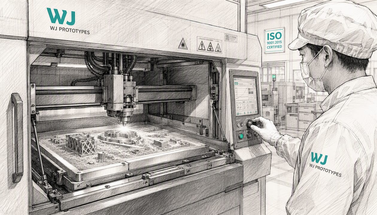

DMLS design guidelines boil down to a short list of numeric rules and process-aware decisions: minimum wall and hole sizes, realistic tolerances, support strategy, and post-process allowances that need to be locked in before a file ever reaches the build queue. The single most important rule is this: minimize solidified volume and build height first, then worry about feature complexity. DMLS success and cost correlate more closely with the amount of material solidified and total layer count than with how intricate a part looks on screen.
Here are the numbers to check against your model right now:
Pro Tip: Attach a one-page notes sheet to your CAD submission listing intended orientation, critical-tolerance surfaces, and target finish. It cuts DFM back-and-forth by at least one full review cycle.
DMLS parts succeed when designers minimize build height and volume, respect material-specific minimum wall and hole sizes, and plan post-process allowances before the first layer prints.
| Point | Details |
|---|---|
| Minimize height and volume first | Cost and failure rate track solidified material and layer count more than geometric complexity. |
| Respect the tolerance baseline | Plan around ±0.005 in for the first inch plus ±0.002 in per additional inch, and machine critical surfaces separately. |
| Design self-supporting angles | Keep overhangs at 30 degrees or steeper from horizontal to avoid most support structures. |
| Plan drain holes in CAD, not after | Retrofitted escape holes often land in low-density core material and cause rework. |
| Get DFM feedback early | WJ Prototypes reviews orientation, wall thickness, and post-process needs during quoting, before the build starts. |
DMLS design rules exist because a focused laser beam, a thin layer of metal powder, and a rapid thermal cycle physically cannot do everything CAD software allows. The laser spot size sets a floor on how thin a wall or how small a hole can be sintered cleanly. Every layer that solidifies also cools, and that cooling generates internal stress that accumulates as the build climbs in height.
Three physical constraints drive nearly every numeric rule in this guide:
Vendors address the thermal problem with a skin/core exposure strategy: the outer shell (skin, roughly 1 mm thick) gets scanned with different parameters than the interior (core), because surface finish and dimensional accuracy matter most at the boundary, while the core just needs to fill in efficiently. This is also why build height and total volume drive cost more than shape complexity. A tall, skinny bracket with simple geometry can cost more to print than a short, complex manifold with the same part footprint, because the machine is charging you for layers and material, not intricacy.
If you’re picturing this, imagine a cross-section of a vertical cylinder next to a horizontal one of equal volume. The vertical version stacks far more thermal cycles on top of each other, and that’s where warping risk concentrates. A quick sketch of orientation against thermal gradient direction is worth doing before you commit to a build plan, even if it’s just a napkin drawing.
Orient parts to protect functional surfaces and minimize the layer count along your most critical dimension, not to make the model look “upright” on screen. EOS guidance is explicit that orientation directly changes surface finish and feature fidelity, so the decision should follow your tolerance map, not habit.
Build volumes vary by machine, but most industrial DMLS systems fall somewhere between roughly 250 x 250 x 300 mm and 400 x 400 x 400 mm. When you’re quoting a job, treat the stated build volume as a planning envelope, not a target to fill. Parts placed too close to the wall of that envelope often show more thermal drift than parts kept toward the center of the plate.
The trade-offs break down like this:
For nesting multiple parts on one plate, keep a consistent bounding-box gap (typically several millimeters minimum) between neighboring parts, avoid clustering tall thin features next to each other where they’ll compete for the same thermal zone, and always confirm how the part attaches to the build substrate, since removal method affects your base surface finish. Our overview of DMLS advantages covers how orientation choices interact with the design freedoms DMLS enables in the first place.
Plan around a working baseline of ±0.005 inch for the first inch of a feature, plus roughly ±0.002 inch for each additional inch, and treat any number tighter than that as something you’ll need to machine into the part after printing, not something DMLS will hand you as-built.

Several factors push actual deviation wider than that baseline. Thermal stress from uneven wall thickness is the biggest offender. Large flat areas warp more than ribbed or curved ones. Support strategy matters too. A face covered in support contact points rarely holds the same flatness as an unsupported top surface. Material choice shifts the numbers as well; titanium alloys tend to hold tighter tolerances than some tool steels because of how each responds to the thermal cycle.
| Feature class | Recommended as-printed tolerance | Recommended post-process tolerance |
|---|---|---|
| Small detail feature (text, emboss) | ±0.1–0.2 mm | Not typically machined |
| General dimension, mid-size part | ±0.005 in first inch, ±0.002 in/in after | ±0.002 inch with CNC finishing |
| Mating face or flange | ±0.2 mm as-built | ±0.02 mm machined |
| Bolt hole / precision bore | Undersized as-built, ream/tap after | ±0.02 mm reamed |
| Large flat surface | ±0.3 mm or worse without support tuning | ±0.002 inch machined and flattened |
Pro Tip: Any surface that mates with another part, seals against a gasket, or carries a press-fit bearing should go straight into the CNC-machining queue in your quote request. Relying on as-printed tolerance for a mating face is the single most common cause of assembly rework we see. If those surfaces are the bottleneck, our CNC machining materials guide covers the finishing options that pair well with DMLS builds.
DMLS typically runs layer thicknesses between 0.02 and 0.1 mm, with skin layers set thinner than the core to protect surface quality. As-built surface roughness, though, varies far more than most designers expect. Vendor data puts it anywhere from 150 to 1,000 microinches Ra depending on material and which way the surface faced during the build.
Upward-facing surfaces generally finish smoother than downward-facing ones that carried support contact. Vertical walls tend to land somewhere in between. If a texture or fine surface detail matters to your part’s function, sand-cast finish expectations don’t apply here. Anything shallower than roughly 0.2 mm in relief risks disappearing into the as-built roughness entirely.
Three finish tiers worth knowing:
If you’re designing a logo, part number, or texture into the surface, specify it deeper and bolder than you would for injection molding. A 0.3 mm deep emboss with generous draft reads far better as-built than a shallow 0.1 mm one that gets lost in the grain.
The practical rule: 0.4 mm is the technical survival floor, 0.8 to 1.0 mm is the recommended minimum for anything load-bearing, and thicker still if the wall stands unsupported and slender. Stainless steels and tool steels can occasionally hold slightly thinner sections than aluminum alloys, which tend to need a bit more margin because of how the material handles thermal shrinkage.
Walls fail below a material-specific threshold because the laser’s minimum sintering width, around 0.6 to 0.9 mm depending on material, sets a hard floor on how thin a continuously fused section can be. Below that width, the wall either doesn’t fully sinter or comes out so brittle it snaps during powder removal.
Design remedies for thin or slender features are straightforward once you know to look for them:
For reference, tool inserts commonly specify a surrounding wall of about 10 mm around cooling channels, a useful benchmark if you’re designing conformal-cooled tooling. A cross-section sketch comparing a bare thin wireframe wall against the same wall with a small internal rib shows the difference immediately: same visual footprint, dramatically different survival odds during powder removal and blasting.
Design through-holes at 1.0 to 1.5 mm minimum diameter for reliable results, and expect anything printed under 5 mm to come out slightly undersized, meaning you should oversize the CAD model if the final bore needs to hit a specific number. Trapped internal channels need extra margin over through-holes because there’s no direct line of sight for laser accuracy or later inspection.
Powder removal is the part everyone underestimates. Any internal channel or cavity needs a planned escape route, and insiders plan those drain holes during CAD creation, not after the fact, because holes added late tend to land in lower-density core material and can compromise thread strength. A good rule: every enclosed cavity gets at least one drain hole at its lowest point in the intended build orientation, sized to let loose powder flow out under vibration, not just gravity.
For threaded features, you have two real options. Print the hole undersized and tap it after the build, which is the standard approach for anything structural, or print threads directly, which works for low-load applications but rarely holds up to repeated fastening cycles. If a tapped hole is critical, add a bore or ream operation to your machining allowance rather than trusting the as-printed bore diameter.
Pro Tip: Model tapped holes with a visible machining stock flag in your CAD file, and note it in your submission notes. A missed 0.3 mm allowance on a bore is a common reason threaded inserts end up loose or cross-threaded after tapping.
Any surface angled less than 30 degrees from horizontal generally needs support, and surfaces below that threshold will show visible roughness or drooping without it. Supports also anchor the part to the build plate and resist warping, so they’re doing double duty even on parts that don’t strictly need overhang support.
Designing to reduce support volume up front is one of the most cost-effective changes you can make before a file ever reaches the queue:
Where supports are unavoidable, design the contact zones deliberately. Small contact islands with sacrificial tips break away more cleanly than broad support webs. Keep support contact off any face you’ve already flagged as a mating or sealing surface, and leave physical access, a hand tool clearance or a slot, so support removal doesn’t require grinding blind. A quick illustration comparing a support field on a functional face versus the same part reoriented to push supports onto a scrap face makes this trade-off obvious at a glance.
The most effective levers, in order, are orientation and support placement, uniform wall thickness, minimized build height, and a post-build stress-relief step. None of these are optional extras. Skip any one of them on a part with mixed section thickness and you’re likely to see warping either during the build or days later once the part relaxes off the plate.
On the design side:
On the process side, machines mitigate stress with inter-layer cooling pauses and island-scan strategies that break large cross-sections into smaller, less thermally continuous patches. After the build, hot isostatic pressing (HIP) closes internal porosity and relieves residual stress under heat and pressure, while a stress-relief anneal alone addresses stress without the porosity benefit. Build-plate constraints also matter: a part released from the plate too early can spring measurably out of tolerance.
Pro Tip: Request HIP for any part with fatigue-critical loading, aerospace or medical brackets especially. Expect it to close internal voids and improve fatigue life, but budget extra lead time. It’s a separate furnace cycle, not a quick add-on.
Most DMLS parts move through the same sequence: build removal from the plate, support removal, stress relief or HIP, heat treatment for the target alloy condition, blasting or media finishing, CNC machining of critical features, and final surface treatment. Skipping the order, machining before stress relief, for example, risks releasing residual stress into a feature you just cut to size.
Plan machining allowance into the CAD model itself, not as an afterthought. A common approach is 0.3 to 0.5 mm of extra stock on any face slated for finish machining, more if the surface sits far from the build plate and is likely to have shifted during the thermal cycle. Blasting, worth noting, changes surface appearance uniformly but can also remove a small, measurable layer of material, so don’t specify it on a feature that’s already at its tolerance limit. Our DMLS manufacturing workflow guide walks through how these steps sequence in an actual production run.
Attach this checklist to every DMLS file you submit for quoting; it’s the single fastest way to cut review cycles down to one round instead of three.
For file formats, submit a native solid CAD file (STEP or similar) alongside an STL with a stated resolution setting, plus a separate PDF or drawing with GD&T callouts on anything dimensionally critical. A model with no GD&T and no notes forces the shop to guess at your intent, and that guess is rarely free.
Vendor ranges vary by machine and material, so treat the table below as a starting point for planning, not a guarantee any specific printer will hit every number.
| Parameter | Typical range |
|---|---|
| Layer height | 0.02–0.1 mm |
| As-built surface roughness | 150–1,000 microinches Ra |
| Working tolerance baseline | ±0.005 in first inch, ±0.002 in/in after |
| Minimum sintering width | 0.6–0.9 mm |
| Common build platform size | roughly 250 x 250 x 300 mm to 400 x 400 x 400 mm |

Material notes worth flagging before you finalize a design: stainless steels tend to hold tighter as-built tolerances than aluminum alloys, which shrink more unevenly during cooling. Tool steels can support thinner conformal wall sections around cooling channels but generally need the full stress-relief and often a secondary heat treat to reach target hardness. If your assembly mixes DMLS components with die-cast housings, note that die casting design follows a different logic entirely, since machining allowance and porosity control drive most of the tolerance conversation there instead of layer-wise thermal stress.
Build inspection access into the model itself, rather than hoping a CMM probe can reach every critical surface after the fact. Flat reference datums, ideally machined after the print rather than left as-built, give a CMM a reliable zero point that as-printed surfaces can’t guarantee given typical roughness values.
For parts with internal features, like conformal cooling channels or lattice structures, consider adding a small witness window or a sacrificial cross-section coupon printed alongside the part on the same plate. That coupon can be sectioned and inspected without cutting into the actual production part, which matters a lot on expensive titanium or Inconel builds. Where GD&T calls out a tight tolerance, make sure the surface is accessible to a probe or gauge; a bore buried behind an unsupported overhang is nearly impossible to verify without disassembly.
Datum flags in the CAD file, not just the drawing, help the shop understand which faces you intend to use for fixturing during machining and inspection. Skipping this step is one of the more common reasons a part passes visual check but fails dimensional verification later.
Design mating interfaces with printed tolerance in mind, not machined tolerance, unless you’ve explicitly specified a finishing pass on that surface. A flange that needs to seal against a gasket, for instance, should almost always get a machined face, since as-built flatness on a broad surface rarely holds tight enough for a reliable seal.
For fasteners, printed threads work for low-load, non-critical joints, but tapped holes remain the standard for anything structural, which means designing extra pilot-hole stock into the model as discussed earlier. Press-fit interfaces need a slightly tighter as-designed clearance than you’d use for a machined part, since as-built surface roughness effectively adds a small amount of interference on its own.
Welding and brazing DMLS parts to other components is possible but demands attention to porosity near the joint; a part that hasn’t gone through HIP is more likely to show weld defects from trapped gas. If an assembly combines a DMLS bracket with a die-cast housing, treat the interface tolerance as the tighter of the two processes’ capabilities, and machine that interface if either side can’t naturally hit the match.
Beyond the general levers already covered, a few specific design moves consistently reduce measured warping on real parts. Gradual wall-thickness transitions matter more than almost anything else; a part that steps abruptly from 2 mm to 8 mm wall thickness concentrates stress at that boundary in a way a tapered transition simply avoids.
Symmetric geometry around the build axis distributes thermal mass evenly, which reduces the tendency for one side of a part to cool and shrink faster than the other. Where symmetry isn’t possible functionally, add temporary stiffening features, a rib or a webbing pattern, that can be machined off after stress relief if they’re not needed in the final part.
Orienting long, thin features parallel to the build plate rather than standing them vertically also reduces the number of thermal cycles they accumulate, which directly reduces distortion risk on exactly the features most likely to warp in the first place.
Titanium alloys (commonly Ti6Al4V) hold tighter as-built tolerances than most other DMLS materials but are considerably more sensitive to support removal; support contact points on titanium often leave witness marks that require more aggressive finishing to clean up. Design support contact zones on titanium parts to land exclusively on non-critical faces.
Aluminum alloys shrink more unevenly during cooling, which means aluminum parts benefit disproportionately from the wall-thickness uniformity rules covered earlier. Skipping that step on an aluminum bracket is one of the more common causes of out-of-tolerance parts in practice.
Stainless steels and tool steels generally tolerate thinner walls and finer detail than aluminum, and tool steels in particular are the material of choice for conformal-cooled inserts, where that 10 mm surrounding wall guideline around cooling channels applies. Each of these alloys reaches full mechanical properties only after the correct post-build heat treatment schedule, so match your material choice to a defined thermal-treatment path before finalizing the design, not after the part comes off the plate.
Every enclosed cavity in a DMLS part is a potential powder trap, and unfused metal powder left inside a finished part isn’t just dead weight. It can rattle loose later and cause failures in moving assemblies. The fix starts in CAD: any internal channel needs a planned entry and exit point sized generously enough for powder to flow out under vibration or light air pressure.
Lattice structures and organic internal geometry are especially prone to trapping powder in low-flow pockets. If your design includes a lattice, model at least one drain path per enclosed region rather than assuming powder will find its own way out through the lattice mesh. For long, narrow channels, a slight taper or a larger exit diameter than entry diameter helps powder flow downhill rather than bridging and clogging partway through.
As mentioned earlier, adding drain holes after the design is finalized is a common source of rework, since retrofitted holes often land in structurally important core material. Build the escape strategy into the part from the first CAD iteration, and treat it with the same seriousness as a load path or a tolerance chain.
Most DMLS rework doesn’t come from exotic geometry. It comes from three repeatable mistakes: designers specify a tolerance tighter than the process can hold without knowing it, they skip drain holes on an internal channel because the CAD looked fine on screen, and they orient a part for visual appeal rather than for the faces that actually carry load or need to seal.
The fix isn’t more advanced software. It’s earlier collaboration. Sending a DFM question before the first quote, rather than after the first failed part, routinely saves an entire iteration cycle. On critical builds, it’s worth submitting a small test coupon alongside the production part on the same build plate, sized to validate wall thickness or hole diameter on the actual machine and material combination rather than trusting a generic datasheet number. That single coupon often answers in one build what three rounds of email back-and-forth would otherwise take to settle.
The other habit worth building: treat your first quote request as a design review, not just a price check. Flag your critical surfaces, state your intended post-process, and ask directly whether your minimum wall or hole spec is realistic for the material you’ve chosen. A shop that answers that question clearly before printing is worth more than one that just quotes the file as submitted.
WJ Prototypes runs ISO-certified DMLS production across a range of metal alloys, including stainless steels, aluminum, and titanium, with in-house DFM review built into every quote rather than bolted on afterward.

That DFM review is where these guidelines actually get applied to your file: our engineers check wall thickness against the material you’ve selected, flag holes and channels that need drain features before they become trapped-powder problems, and recommend orientation based on which surfaces you’ve marked critical, not just what looks efficient on the build plate. Parts that need tighter tolerances than DMLS delivers as-built move straight into our CNC machining queue without a separate vendor handoff, and stress relief, HIP, or heat treatment gets scheduled as part of the same production run instead of a disconnected afterthought. If you’re ready to move from guideline to build, submit your CAD file through our DMLS 3D printing quote page and include the pre-submission checklist notes from this guide. It’s the fastest way to get a quote back with real DFM feedback attached, not just a price.
Most vendors put the technical survival floor around 0.4 mm, but 0.8 to 1.0 mm is the recommended minimum for any wall that carries structural load, with thicker margins for slender, unsupported sections.
For DMLS specifically, the three that matter most are minimizing build height and volume, designing self-supporting angles to reduce support needs, and planning realistic tolerances that account for thermal stress rather than assuming machined-part precision.
Yes, in most cases. Supports anchor the part to the build plate, resist warping, and hold up overhangs below roughly 30 degrees from horizontal, though careful orientation and design can significantly reduce how much support a given part needs.
No. DMLS and selective laser melting (SLM) are closely related metal powder bed fusion processes, but they differ in how fully the metal is melted versus sintered and in typical machine and material specifications. Our DMLS vs SLM comparison breaks down which process fits which application.
Any mating face, sealing surface, or precision bore that needs tighter tolerance than roughly ±0.005 inch for the first inch should go into the machining allowance from the start, since as-built DMLS surfaces aren’t designed to hit that precision alone.
SERVICES
RESOURCES