


- Room 1807, Unit 9, Building 2, Shangxing Commercial Street, Shangde Road, Shangxing Community, Xinqiao Subdistrict, Bao'an District, Shenzhen City, China
CONTACT US

WhatsApp

Contact Us
Our team is on stand by, waiting toassist you.
Videos
A large collection of educational videos and tutorials.
About Us
Learn about our company, leadership, and mission totransform manufacturing.
Privacy Policy
Applies to all personal information collected through and/or processed in connection.

Aerospace & UAV
WJ Prototypes is your 3D manufacturing partner from prototype to large scale production.
Consumer Electronics
New Product Introduction Solutions for Consumer Electronics.

Robotics & Automation
Need some assistance bringing your robotic device or parts from the sketch-board to reality?
Medical Devices
The medical industry needs high quality, dependable and safe parts and products.
Automotive
New Product Introduction Solutions for Automotive
Industrial Machinery
The main purpose of industrial prototyping is to take the product from drawings into the real world.

TL;DR:
Mastering DMLS workflow discipline ensures high-quality, flight-ready metal parts within days.
Proper design preparation, material certification, and process monitoring are critical for success.
Workflow optimization reduces rejection rates, accelerates certification, and improves project reliability.
When a prototype iteration cycle runs two weeks over schedule, it rarely stays an isolated problem. In aerospace and automotive development, a single rework loop can push back tooling decisions, supplier commitments, and regulatory submissions all at once. Direct Metal Laser Sintering, or DMLS, was built to break that cycle. It delivers complex, flight-ready metal parts in days rather than weeks, but only when the workflow behind it is managed with discipline. This guide walks you through every stage of the DMLS process, from design preparation through final inspection, so your team can move faster, reject less, and hit launch windows with confidence.
| Point | Details |
|---|---|
| DMLS enables rapid metal prototyping | Direct Metal Laser Sintering delivers fast, complex parts that meet aerospace and automotive standards. |
| Workflow preparation is essential | Proper design, material selection, and setup dramatically increase print success and quality. |
| Process control ensures reliability | Monitoring parameters and post-processing techniques are critical for consistent, high-performance results. |
| Workflow optimization adds long-term value | Continuous improvement and team training future-proof manufacturing operations for evolving industry needs. |
DMLS is a powder bed fusion process that uses a high-powered laser to selectively fuse metal powder, layer by layer, into fully dense parts. Unlike casting or machining, it requires no hard tooling, which makes it ideal for rapid iteration in aerospace brackets, automotive heat exchangers, and other geometrically complex components. DMLS enables precision metal prototyping with reduced lead times, a critical advantage when design cycles are compressed and physical validation cannot wait.
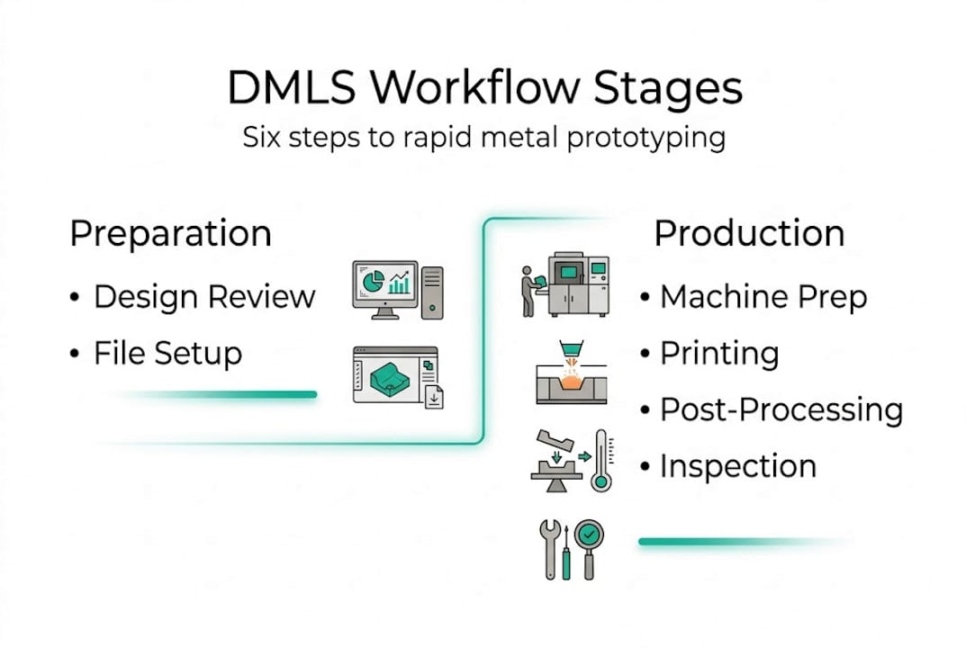
The overall workflow breaks into six connected stages: design preparation, build file setup, machine preparation, printing, post-processing, and inspection. Each stage feeds the next, and a mistake in stage one will compound through every step that follows. Understanding this linear dependency is the first shift in mindset that separates teams who succeed with DMLS from those who treat it like a conventional machine tool.
To put DMLS in context against other additive manufacturing types, consider the following comparison:
| Method | Material output | Workflow complexity | Typical lead time | Best use case |
|---|---|---|---|---|
| DMLS | Metal alloys | High | 3 to 7 days | Functional metal prototypes |
| SLS | Nylon/polymers | Medium | 2 to 5 days | Structural plastic parts |
| SLA | Photopolymer resin | Low | 1 to 3 days | Visual and form models |
| MJF | Nylon/TPU | Medium | 2 to 4 days | Complex polymer geometries |
Beyond the machine itself, a capable DMLS workflow demands a specific set of tools and skills on your team:
Pro Tip: Involve your manufacturing engineer in the design review before the STL file is ever generated. Catching a problematic overhang or unsupported wall at the CAD stage costs minutes. Catching it after a failed build costs days.
Explore competitive DMLS 3D Printing with expert support from WJ Prototypes.
Whether you're comparing suppliers or looking to optimize costs, our team can help you evaluate the best option for your project.
👉 Request A Quote now or email us at info@wjprototypes.com to get started.
Preparation is the cornerstone for success in DMLS. Effective preparation translates directly to higher part quality and lower rejection rates, and this is especially true when you are working with safety-critical aerospace or automotive components.
Start with a thorough design review. Your CAD model should comply with DMLS-specific guidelines: minimum wall thickness of 0.4 mm, overhang angles kept below 45 degrees without support, and internal channels designed for powder evacuation. Once the geometry is validated, export a clean STL file with a resolution fine enough to preserve critical surface features without bloating file size.
Material selection follows design validation. The table below summarizes common DMLS materials used in aerospace and automotive applications:
| Material | Density (g/cm3) | Tensile strength (MPa) | Typical application |
|---|---|---|---|
| Ti6Al4V | 4.43 | 1100 | Aerospace brackets, implants |
| AlSi10Mg | 2.67 | 400 | Automotive housings, heat sinks |
| Inconel 718 | 8.19 | 1240 | Turbine components, high-heat parts |
| 316L Stainless Steel | 7.99 | 540 | Fluid systems, structural parts |
| Maraging Steel | 8.00 | 1900 | Tooling inserts, high-load fixtures |
With material chosen, follow these ordered preparation steps:
For aerospace additive manufacturing examples, you will see that teams who skip formal powder certification frequently encounter porosity defects that fail X-ray inspection.
Pro Tip: Always request a material certification document from your powder supplier, including particle size distribution and chemical composition. For AS9100 or IATF 16949 traceability, this document is not optional.
With preparation in place, the actual printing process demands careful attention to detail and safety. Process monitoring and parameter control are the backbone of reliable DMLS printing, and skipping even one monitoring checkpoint can result in a scrapped build.
Follow these steps for a controlled machine startup and print initiation:
Safety warning: DMLS machines use high-powered fiber lasers and fine reactive metal powders. Never open the build chamber during operation. Metal powder inhalation is a serious health hazard. Always use N95 or P100 respirators, grounded anti-static gloves, and follow your facility's powder handling SOP before and after every build.
During the build, your monitoring focus should cover three signals: recoater blade behavior, melt pool consistency visible through the machine camera, and any error codes on the machine console. A streaked recoater pass often signals a crashed part or a blade chip. Melt pool irregularities can indicate parameter drift or contaminated powder.
Mid-build intervention is only advisable when you detect a definitive structural failure, such as a part detaching from the build plate or a recoater jam. Pausing for minor anomalies usually causes more damage than letting the build run. Review the traditional manufacturing differences to understand why DMLS process interruptions carry risks that a milling operation would not.
After the part is printed, the final workflow pieces ensure readiness and reliability for application use. Post-processing in DMLS is not a cleanup step. It is a critical engineering phase that directly affects mechanical properties and dimensional accuracy.

Begin with controlled powder removal. Use a dedicated powder recovery station to extract loose powder from the build chamber and internal channels. Recovered powder can be sieved and blended back with virgin powder at approved ratios. Next, cut support structures using EDM wire cutting or manual tools, depending on geometry and material. Avoid aggressive grinding near functional surfaces.
For most aerospace and structural automotive parts, stress relief heat treatment is mandatory after support removal. This step reduces residual stresses introduced during the rapid heating and cooling of the laser process. Titanium and Inconel parts typically require hot isostatic pressing as well, which closes internal microporosity and brings density above 99.9%.
Inspection protocols then follow in sequence. Quality control is vital for ensuring end-use part reliability in DMLS, and a layered inspection approach is the industry standard:
For ongoing workflow optimization, consider these efficiency improvements:
Refer to the precision prototyping guide for a detailed breakdown of how digital workflow integration reduces cycle time across iterative builds.
| Workflow stage | Common bottleneck | Efficiency tweak |
|---|---|---|
| Design prep | Overhang violations caught late | Run DfAM check before STL export |
| Build setup | Support generation time | Use parametric support templates |
| Printing | Unplanned build failures | Monitor first 20 layers actively |
| Post-processing | Heat treatment scheduling delays | Pre-book furnace slots at build start |
| Inspection | CT scan backlog | Batch CT with mechanical testing |
Here is the uncomfortable reality most DMLS vendors will not tell you: the machine is the easy part. Any well-funded team can purchase a DMLS system. What separates programs that consistently deliver certified, flight-ready parts from those that struggle with scrap rates and audit failures is workflow discipline, not hardware.
A common misconception is that DMLS is plug-and-play once you have the right machine and material. In practice, teams that treat it that way spend months chasing porosity defects, dimensional drift, and inconsistent mechanical properties. We have seen real-world aerospace examples where structured workflow optimization, specifically tightening parameter windows and formalizing powder traceability, cut part rejection rates by more than 40% within two build cycles.
The other payoff is certification speed. AS9100 and IATF 16949 auditors do not just inspect parts. They inspect your process documentation, your traceability chain, and your corrective action records. A mature DMLS workflow already generates most of that evidence as a byproduct of good practice.
Pro Tip: Embed a DMLS process specialist directly in your design team, not just in the shop. When the person who understands laser parameters and powder behavior sits in the same design review as your stress analyst, you eliminate entire categories of rework before the first build ever runs.
For those ready to accelerate DMLS projects, partnering with workflow specialists makes all the difference. At WJ Prototypes, our DMLS 3D printing services are backed by experienced process engineers who manage every stage from design review through final inspection. We work with aerospace and automotive teams globally, supporting rapid iteration cycles with certified materials, validated parameters, and documented traceability. Whether you need a single functional prototype or a low-volume production run, our instant quoting platform gets your project moving fast. Explore our full range of CNC machining materials to complement your DMLS parts with precision-machined components in the same workflow.
DMLS enables rapid production of complex, high-strength metal components that traditional methods cannot achieve with the same lead time. Reduced lead times make it especially valuable when design iterations are frequent and physical validation cannot be delayed.
Popular CAD tools like SolidWorks and Siemens NX are widely used for DMLS design and STL export, typically paired with build prep software like Materialise Magics. Effective preparation at this stage directly determines part quality and rejection rates downstream.
Key steps include powder removal, support structure separation, and heat treatment or hot isostatic pressing as required by the material and application. End-use part reliability depends on completing each post-processing stage in the correct sequence.
DMLS can produce parts faster and with far greater geometric freedom, but it requires careful workflow control to achieve consistent mechanical properties. Parameter control and process monitoring are what make the difference between a reliable production workflow and an unpredictable one.
What Is DMLS? Precision Metal Prototyping Explained
Additive Manufacturing Workflow for Prototyping Success
Sheet Metal Fabrication Workflow for Prototyping in China
7 Essential Types of Rapid Prototyping for Engineers
Explore competitive DMLS 3D Printing with expert support from WJ Prototypes.
Whether you're comparing suppliers or looking to optimize costs, our team can help you evaluate the best option for your project.
👉 Request A Quote now or email us at info@wjprototypes.com to get started.
SERVICES
RESOURCES


