


- Room 1807, Unit 9, Building 2, Shangxing Commercial Street, Shangde Road, Shangxing Community, Xinqiao Subdistrict, Bao'an District, Shenzhen City, China
CONTACT US

WhatsApp

Contact Us
Our team is on stand by, waiting toassist you.
Videos
A large collection of educational videos and tutorials.
About Us
Learn about our company, leadership, and mission totransform manufacturing.
Privacy Policy
Applies to all personal information collected through and/or processed in connection.

Aerospace & UAV
WJ Prototypes is your 3D manufacturing partner from prototype to large scale production.
Consumer Electronics
New Product Introduction Solutions for Consumer Electronics.

Robotics & Automation
Need some assistance bringing your robotic device or parts from the sketch-board to reality?
Medical Devices
The medical industry needs high quality, dependable and safe parts and products.
Automotive
New Product Introduction Solutions for Automotive
Industrial Machinery
The main purpose of industrial prototyping is to take the product from drawings into the real world.


TL;DR:
DMLS significantly reduces material waste and weight in aerospace parts by enabling complex lattice architectures. It allows for faster design iterations, consolidated components, and cost-effective production of certified flight components. Embracing true design freedom with DMLS unlocks advanced, lightweight, and efficient aerospace structures.
When a titanium bracket starts its life as a billet that weighs twenty times the finished part, you know traditional aerospace manufacturing has a problem. The role of DMLS in aerospace is precisely to solve that problem, along with several others that CNC machining and conventional fabrication cannot touch. Direct Metal Laser Sintering (DMLS), a powder bed fusion process that fuses metallic powders layer by layer using a high-powered laser, is reshaping how aerospace engineers approach everything from structural prototypes to flight-certified components. This article breaks down the technology, its real-world applications, certification requirements, and the design thinking shift it demands.
| Point | Details |
|---|---|
| DMLS reduces aerospace material waste | Direct Metal Laser Sintering minimizes material scrap by producing near-net-shape parts with buy-to-fly ratios close to 1.1:1. |
| Enables complex lightweight designs | DMLS allows fabrication of advanced lattice structures and integrated assemblies impossible with traditional machining. |
| Accelerates prototyping and production | DMLS shortens development cycles through fast, precise metal part production suitable for low-volume aerospace runs. |
| Certified parts meet strict standards | Aerospace components made with qualified DMLS processes can comply with stringent certification requirements like ESA ECSS. |
| Partner with experienced providers | Collaborating with experts like WJ Prototypes ensures efficient implementation of DMLS in aerospace manufacturing workflows. |
DMLS works by directing a laser across a bed of fine metal powder, selectively melting each layer according to a CAD file, then lowering the build platform and repeating the process. Unlike CNC machining, which removes material from a solid billet, DMLS adds material only where it is needed. That difference is the foundation of nearly every advantage the process offers aerospace manufacturers.
The numbers tell the story clearly. Traditional aerospace machining of titanium or nickel superalloys routinely produces a buy-to-fly ratio of 15:1 or even 20:1, meaning you buy and waste 15 to 20 kilograms of expensive alloy for every kilogram that actually flies. DMLS drives that ratio close to 1.1:1. For aerospace-grade titanium at roughly $200 per kilogram, that gap in material consumption becomes a decisive cost factor on any program.
Beyond raw material savings, DMLS enables what engineers call Design for Performance (DfP) rather than the traditional Design for Manufacture (DfM). DfM constrains geometry to what a mill or lathe can physically reach. DfP asks a different question entirely: what shape does physics actually want this part to be? The answer is almost always something a five-axis CNC machine cannot produce.
Key benefits that aerospace procurement managers and R&D teams consistently cite include:
You can get a detailed breakdown of how the process works in practice in this DMLS metal prototyping overview covering materials, tolerances, and surface finish expectations.
Pro Tip: When evaluating DMLS for a new aerospace program, calculate your alloy cost per kilogram multiplied by the buy-to-fly ratio difference. For titanium components, this single comparison often justifies the switch before you factor in any other benefit.
The most significant structural advantage DMLS delivers is the ability to build lattice architectures, open-cell or closed-cell periodic structures that carry load efficiently while removing mass from regions where stress is low. A solid aluminum block and a lattice-filled aluminum component of identical external dimensions can have a 40 to 65 percent difference in mass, with surprisingly similar stiffness under primary load cases.

Research published in 2026 demonstrated this with precision. A lattice-based design using DMLS achieved a 64.6% mass reduction in helicopter landing gear while preserving full load capacity, using AlSi10Mg aluminum alloy with a parametric design framework that coupled CAD modeling directly to finite element analysis. That is not a theoretical result from a university lab. It is a structural aerospace component validated against real load cases.
What makes this achievable is the integration of CAD and CAE tools at the design stage. Topology optimization software identifies which regions of a part carry significant stress, and lattice generation algorithms fill the remaining volume with periodic struts sized to meet stiffness and buckling requirements. DMLS then builds exactly what the simulation specifies, without the geometric compromises that traditional manufacturing would impose.
| Design parameter | Traditional machined part | DMLS lattice-optimized part |
|---|---|---|
| Mass reduction potential | 5 to 15% | 40 to 65% |
| Internal feature access | Severely limited | Unrestricted |
| Assembly count | Often multi-part | Single printed body |
| Design iteration speed | Weeks (tooling required) | Days (file revision only) |
| Load path optimization | Constrained by geometry | Fully topology-optimized |
There are real challenges here. Thin lattice struts, typically 0.3 to 1.0 mm in diameter, require tightly controlled laser parameters to maintain dimensional accuracy and prevent powder adhesion inside the structure. Overhanging struts without adequate support angle can deflect during printing. These are solvable problems, but they require engineers who understand DMLS process constraints from the start of design, not at the end.
See real-world additive manufacturing examples for aerospace that illustrate how these structural principles translate into finished components.
Pro Tip: When designing lattice structures for DMLS, target strut diameters above 0.4 mm and self-supporting angles above 45 degrees to minimize build failures and reduce post-processing time. Validate these parameters with your DMLS supplier before committing to a full production design.
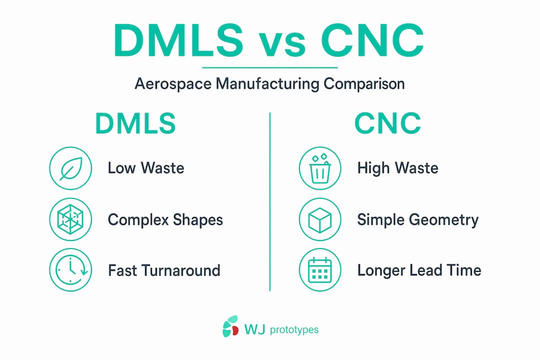
Comparing DMLS directly to conventional methods reveals where the technology earns its place and where its limitations still matter. CNC machining delivers excellent dimensional accuracy, particularly for large monolithic structures, and it is the only appropriate choice for many finishing operations. But for parts with complex internal geometry, low production volumes, or aggressive weight targets, the comparison shifts decisively.
Traditional subtractive machining of aerospace alloys involves:
DMLS addresses each of these directly. The buy-to-fly ratio reduction from 15:1 to near 1.1:1 cuts raw material cost substantially, and weight savings through lattice topology can reach 55% compared to solid machined equivalents. A single DMLS part can replace an assembly of five or ten machined and welded pieces, eliminating all the fasteners, weld inspection requirements, and assembly labor associated with that joint count.
The DMLS manufacturing workflow from file to finished part typically runs two to four weeks for aerospace-grade components, including post-processing and basic inspection, compared to eight to sixteen weeks for complex machined assemblies requiring multiple suppliers. That schedule compression matters acutely during prototype iterations and when responding to design changes during development programs.
To understand where DMLS prototyping adds the most value relative to cost, review the benefits of DMLS prototyping for a structured comparison across production scenarios.
The practical applications of DMLS across aerospace sectors have moved well beyond demonstrators and one-off prototypes. Qualified production components now fly in commercial turbofan engines, are integrated into satellite structures, and form critical structural elements in rotorcraft.
Here are four categories of aerospace components where DMLS has achieved documented production status:
Industry milestone: GKN Aerospace's production of 600-plus DMLS fan case mount rings for Pratt & Whitney is one of the clearest signals that DMLS aerospace components have achieved the reliability and repeatability standards required for certified powerplant applications.
Explore the full range of aerospace DMLS manufacturing applications and production capabilities to assess fit for your specific program requirements.
Certification is where many DMLS programs get complicated, and where unprepared teams lose time and budget. Aerospace qualification of additively manufactured metal parts is not simply a matter of printing a part and sending it for mechanical testing. The process requires validating the entire manufacturing chain, from powder feedstock through final dimensional inspection.
A qualification procedure for titanium space components following ESA ECSS standards demonstrated what a rigorous building-block approach looks like: powder characterization first, then specimen-level tensile and fatigue testing, then sub-component structural testing, and finally prototype-level performance verification under flight load cases. Each level of the pyramid must pass before the next begins.
Key elements of an aerospace DMLS qualification program include:
The time and cost investment in qualification is substantial. But qualified additive manufacturing processes often reduce recurring certification burden for subsequent production runs compared to traditional methods, because the process, not just the part, is what is being certified.
Check out these DMLS prototyping benefits for engineers for a practical discussion of how early-stage prototyping can accelerate your path to full qualification.
Pro Tip: Build your qualification powder database early. Mechanical properties in DMLS are sensitive to powder lot variation, and having traceability from powder certificate to flown part is not optional in aerospace. Establish your approved supplier list and powder re-certification protocol before your first production build.
Here is an uncomfortable truth that rarely gets said plainly in aerospace circles: most engineers still design DMLS parts the same way they would design machined parts. They use the technology's material properties but ignore its geometry freedom. That is like buying a turbofan engine and using it as a paperweight.
The most transformative DMLS programs are the ones where engineers stop asking "can we make this shape with the printer?" and start asking "what shape does this load case actually want?" Industry analysis confirms that DMLS enables Design for Performance, allowing organic shapes and lattice architectures that CNC machining cannot produce, and that this design philosophy is what unlocks maximum lightweighting potential. The technology is not a substitute for traditional machining. It is a fundamentally different engineering tool that requires a fundamentally different design methodology.
From our experience working with aerospace R&D teams, the programs that fail to capture DMLS's full value share a common pattern: they bring the printer in at the end of a design process built around subtractive manufacturing constraints. The programs that succeed integrate topology optimization and additive design rules from the first concept sketch.
The practical shift required is not primarily technological. It is organizational. CAD and CAE tools for additive design exist. The barrier is getting structural analysts, designers, and manufacturing engineers to collaborate at the concept stage instead of sequentially. Teams that make this shift are compressing development cycles and producing lighter, more reliable structures. Teams that do not are paying DMLS prices for machined part geometries.
Explore the broader landscape of additive manufacturing types to understand where DMLS sits relative to other processes and when it is the right choice versus polymer-based or binder jetting alternatives.
Translating DMLS design principles into production-ready aerospace components requires a manufacturing partner with proven process controls, material expertise, and the engineering support to move from CAD file to qualified part without unnecessary delays. WJ Prototypes offers DMLS manufacturing services specifically suited to aerospace prototyping and low-volume production, with the quality systems, material traceability, and dimensional inspection infrastructure that aerospace programs demand. For programs requiring integrated metal and structural assemblies, WJ Prototypes also provides CNC machining services and access to a broad CNC machining materials library covering aerospace alloys. Sheet metal enclosures, brackets, and secondary structures are supported through a complete sheet metal materials portfolio, enabling single-source supply for complex aerospace assemblies. Contact WJ Prototypes to discuss your program requirements and receive a fast quote.
Explore competitive Rapid Prototyping Services with expert support from WJ Prototypes.
Whether you're comparing suppliers or looking to optimize costs, our team can help you evaluate the best option for your project.
👉 Request A Quote now or email us at info@wjprototypes.com to get started.
Aluminum alloys like AlSi10Mg, titanium alloys such as Ti6Al4V, and high-performance nickel-based superalloys are the primary choices, each offering a specific combination of strength, density, and thermal resistance suited to different aerospace DMLS parts. The ARCAM A2X system manufactures Ti6Al4V titanium alloy parts directly compatible with aerospace composite structures.
DMLS achieves a buy-to-fly ratio near 1.1:1, reducing material waste to under 10%, compared to traditional CNC ratios often exceeding 15:1 for titanium and superalloy components, which represents a dramatic cost reduction for expensive aerospace alloys.
Yes. When manufactured through a validated process and tested following structured qualification frameworks, DMLS parts reliably meet aerospace certification requirements. Qualification of titanium DMLS parts following ESA ECSS standards with a building-block approach validated performance at powder, specimen, and prototype levels.
Helicopter landing gear lattice structures, satellite structural panels, and turbofan engine mount rings have all been produced at scale. GKN Aerospace achieved full-rate production of over 600 DMLS fan case mount rings for Pratt & Whitney engines, establishing a clear precedent for flight-certified additive parts.
Maintaining strut integrity in lattice structures, ensuring consistent powder flowability and lot traceability, managing build failures from complex overhanging geometry, and navigating the full certification process are the primary challenges. DMLS lattice printing requires tightly optimized laser parameters and validated powder properties to achieve the repeatability aerospace programs demand.
DMLS Manufacturing Workflow: Step-by-Step Guide for Rapid Prototyping
DMLS In Prototyping: Benefits For Engineers In 2026
Why Choose DMLS For High-Performance Prototyping
DMLS 3D Printing In China | Get A Quick Quote for DMLS 3D Printing Services
Explore competitive Rapid Prototyping Services with expert support from WJ Prototypes.
Whether you're comparing suppliers or looking to optimize costs, our team can help you evaluate the best option for your project.
👉 Request A Quote now or email us at info@wjprototypes.com to get started.
SERVICES
RESOURCES


