


- Room 1807, Unit 9, Building 2, Shangxing Commercial Street, Shangde Road, Shangxing Community, Xinqiao Subdistrict, Bao'an District, Shenzhen City, China
CONTACT US

WhatsApp

Contact Us
Our team is on stand by, waiting toassist you.
Videos
A large collection of educational videos and tutorials.
About Us
Learn about our company, leadership, and mission totransform manufacturing.
Privacy Policy
Applies to all personal information collected through and/or processed in connection.

Aerospace & UAV
WJ Prototypes is your 3D manufacturing partner from prototype to large scale production.
Consumer Electronics
New Product Introduction Solutions for Consumer Electronics.

Robotics & Automation
Need some assistance bringing your robotic device or parts from the sketch-board to reality?
Medical Devices
The medical industry needs high quality, dependable and safe parts and products.
Automotive
New Product Introduction Solutions for Automotive
Industrial Machinery
The main purpose of industrial prototyping is to take the product from drawings into the real world.

TL;DR:
DMLS produces fully dense, high-performance metal parts suitable for critical applications.
It enables complex geometries and design features impossible with traditional manufacturing methods.
Post-processing and stress management are essential for achieving optimal part quality and performance.
Metal 3D printing has a reputation problem. Many product teams still treat it as a shortcut for quick-look models, not a serious manufacturing path. That assumption costs them time, money, and competitive ground. DMLS (Direct Metal Laser Sintering) delivers >99.5% density in finished metal parts, matching wrought material performance while enabling geometries that CNC machining and casting simply cannot produce. For aerospace, automotive, medical, and robotics teams pushing the limits of what metal components can do, DMLS is not a workaround. It is a strategic manufacturing choice. This guide breaks down exactly why.
| Point | Details |
|---|---|
| Unmatched design freedom | DMLS lets you create complex metal parts and consolidated designs unreachable via CNC or casting. |
| Superior material efficiency | Reduce material waste and part weight by up to 40% or more with DMLS compared to traditional methods. |
| Rapid prototyping cycle | Accelerate development with tool-free iteration and lead times cut from weeks to days. |
| Certification and post-processing essentials | Success with DMLS requires expert management of stress relief, anisotropic properties, and rigorous post-processing. |
| Best-fit for low-medium volume, high-performance parts | DMLS excels where complexity and alloy strength are critical, especially in aerospace, automotive, medical, and robotics sectors. |
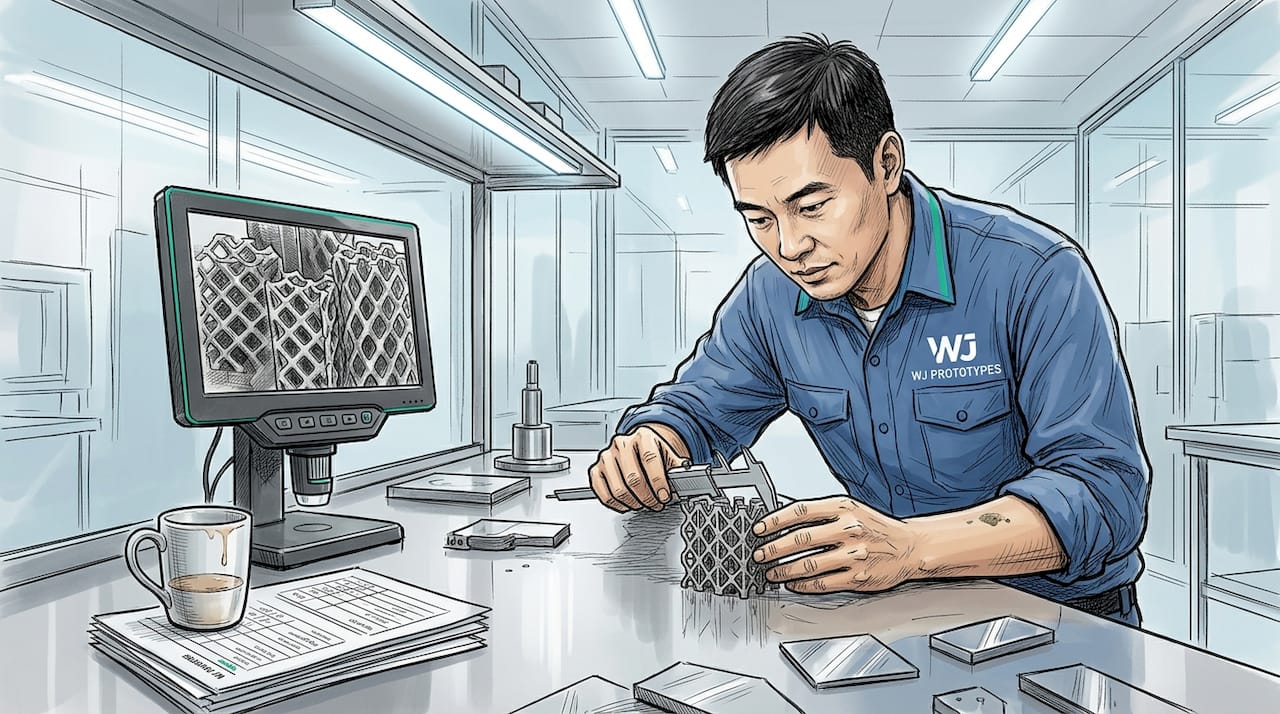
Direct Metal Laser Sintering is a powder bed fusion process. A high-powered laser selectively melts thin layers of metal powder, fusing them into a solid part layer by layer. Each layer is typically 20 to 60 microns thick. The build chamber is flooded with inert gas, usually argon or nitrogen, to prevent oxidation during the melt. Once the build is complete, the part is removed from the powder bed, support structures are detached, and post-processing begins.
Here is the step-by-step breakdown of a standard DMLS build:
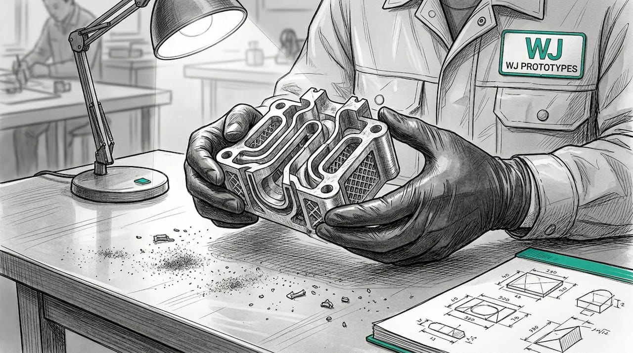
The result is a fully dense metal part. DMLS achieves >99.5% density in alloys like Ti-6Al-4V (950 to 1100 MPa UTS) and Inconel 718 (1000 to 1200 MPa UTS), performance numbers that rival forged and wrought equivalents. That is why DMLS metal prototyping is increasingly specified for flight hardware, surgical implants, and high-load robotics joints, not just concept models.
Among the many additive manufacturing types available today, DMLS stands out for its ability to process reactive and high-temperature alloys that other processes cannot handle. Following 3D prototyping best practices from the start of a project dramatically reduces iteration cycles and cost.
Pro Tip: Always build test coupons alongside your actual part in the same build job. These coupons undergo the same thermal history as your part and provide the mechanical data you need for certification. Skipping this step is the single most common mistake teams make when qualifying DMLS parts for regulated industries.
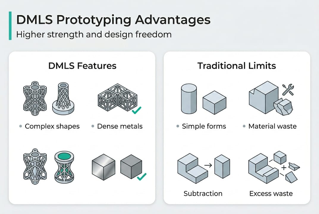
CNC machining is precise, fast, and reliable for many applications. But it is fundamentally subtractive. You can only remove material that a cutting tool can physically reach. Casting requires tooling, draft angles, and wall thickness constraints that drive design compromises. DMLS has none of those constraints. The laser does not care whether your part has internal lattices, branching channels, or organic topology-optimized geometry.
DMLS enables complex geometries, including internal channels, lattice structures, and part consolidation that are simply impossible with CNC or casting. GE Aviation's fuel nozzle is the most cited example: a part previously assembled from 18 separate components was redesigned as a single DMLS build. It ran 25% more efficiently and lasted five times longer. That is not an incremental improvement. It is a product architecture shift.
For aerospace additive manufacturing, conformal cooling channels in tooling inserts can reduce injection molding cycle times by 20 to 40%. Medical implants with trabecular lattice structures promote osseointegration in ways that solid cast implants cannot. Robotics end-effectors can be lightweighted without sacrificing stiffness by using topology-optimized internal geometry.
Here are some DMLS-enabled features that traditional manufacturing cannot replicate:
| Feature | DMLS | CNC machining | Casting |
|---|---|---|---|
| Internal channels | Yes | Limited | Limited |
| Lattice structures | Yes | No | No |
| Part consolidation | Yes | No | Partial |
| Tool-free production | Yes | No | No |
| Geometric complexity | Very high | Medium | Medium |
For teams exploring rapid prototyping types, DMLS is the only option that delivers production-representative metal parts without tooling investment. DMLS for weight reduction in structural aerospace components is now a well-documented application, not an experimental one.
Pro Tip: Design for DMLS from day one. Orient your part to minimize support structures on functional surfaces, and design self-supporting angles above 45 degrees wherever possible. Retrofitting a CNC design into a DMLS build almost always results in unnecessary supports, longer post-processing, and higher cost.
Material waste is a silent cost driver in traditional metal manufacturing. CNC machining of titanium aerospace brackets routinely produces buy-to-fly ratios of 15:1 to 20:1, meaning you machine away 14 to 19 kg of expensive titanium to get 1 kg of finished part. DMLS flips that equation. The buy-to-fly ratio drops to roughly 1.1:1, and unused powder is recycled back into the next build.
The performance numbers are equally compelling. DMLS achieves >99.5% density with higher ultimate tensile strength than casting in alloys like AlSi10Mg and Ti-6Al-4V. Combined with topology optimization and lattice infill strategies, teams regularly achieve up to 55% weight reduction in aerospace structural components without sacrificing load-bearing performance.
| Metric | DMLS | CNC machining | Casting |
|---|---|---|---|
| Buy-to-fly ratio | ~1.1:1 | 15:1 to 20:1 | ~1.3:1 |
| Density | >99.5% | 100% (solid) | 95 to 99% |
| Weight reduction potential | Up to 55% | Low | Low |
| Tooling required | No | No | Yes |
Here is how to leverage DMLS material advantages systematically:
For teams evaluating the rapid prototyping benefits of DMLS versus alternatives, the material efficiency argument alone often justifies the per-part cost premium over CNC for complex geometries. Learn more about DMLS 3D printing capabilities and how they translate to real production scenarios. For a detailed look at DMLS manufacturing time and cost drivers, build time per layer and part volume are the primary variables to model.
No manufacturing process is without trade-offs, and DMLS is no exception. The rapid heating and cooling cycles that give DMLS its density also generate significant residual stresses within the part. Without proper stress relief heat treatment, those stresses can cause distortion or cracking, especially in large, thin-walled sections. High residual stresses from rapid heating and cooling are the primary cause of build failures and dimensional inaccuracy in DMLS.
Anisotropy is another real concern. DMLS parts can show 10 to 20% variance in mechanical properties between the build direction (Z-axis) and the XY plane. For parts with critical load paths in multiple directions, this matters. Design orientation and post-processing choices both affect the final anisotropy profile.
Post-processing for DMLS is extensive by default. As-built surface roughness runs Ra 10 to 25 microns, compared to Ra 1 to 4 microns for cast parts. Achieving tighter tolerances and smoother finishes requires machining, grinding, or electropolishing after the build. Typical post-processing steps include:
"Test coupons from the same build are essential for certification. They share the same thermal history as the production part and provide the only valid basis for mechanical property qualification in regulated industries."
For teams comparing CNC vs DMLS materials or evaluating CNC machining cost comparison against additive alternatives, the post-processing burden is a critical factor in total cost modeling. Research on DMLS part properties confirms that HIP treatment significantly narrows the fatigue performance gap between DMLS and wrought materials.
Most teams evaluate DMLS on a cost-per-part basis and walk away thinking it is too expensive. That framing misses the point entirely. The real question is: what does it cost to prototype with traditional methods when you need three design iterations, two rounds of tooling, and six weeks of lead time? DMLS eliminates tooling entirely and compresses that cycle to days.
What we see consistently is that teams underestimate design freedom and then underestimate post-processing complexity in equal measure. They get excited about the geometry possibilities and then are surprised when the part needs stress relief, HIP, and machining before it is ready for testing. Both sides of that equation need to be planned for upfront.
The ideal DMLS application has three characteristics: low to medium volume, complex geometry that cannot be machined or cast economically, and a high-performance alloy requirement. When all three align, DMLS is almost always the right answer. When only one or two apply, the trade-off analysis gets more nuanced.
Critically, SLM and DMLS tensile strength often exceeds casting, but fatigue performance is typically lower without HIP treatment. Teams qualifying parts for flight or implant use need to account for this in their design margins and test plans. Precision DMLS prototyping done right means designing for the process from the first CAD file, not adapting a legacy design after the fact.
If your team is ready to move from concept to certified metal parts faster and with more design freedom than traditional methods allow, WJ Prototypes offers the full ecosystem to make that happen. From DMLS 3D printing services in high-performance alloys to hybrid workflows that combine additive builds with precision CNC machining services for critical tolerances, WJ Prototypes supports aerospace, automotive, medical, and robotics teams at every stage. ISO-certified processes, experienced engineers, and global delivery mean your parts meet spec and arrive on schedule. Request an instant quote and connect with a team that understands what demanding applications actually require.
DMLS can produce end-use parts with high density and strength, but is best for low to medium volumes or complex geometries where traditional methods fall short. High-volume, simple-geometry parts are usually better served by CNC or casting.
DMLS uses high-performance alloys including Ti-6Al-4V, Inconel 718, and AlSi10Mg, delivering mechanical properties close to wrought materials at densities above 99.5%. Stainless steel and cobalt-chrome are also widely processed.
DMLS parts generally have higher tensile strength than cast parts, but fatigue performance is lower unless hot isostatic pressing is applied to close residual microporosity and improve fatigue life.
DMLS involves residual stresses, anisotropic properties, and mandatory post-processing. Thin walls below 0.4 mm and large unsupported overhangs increase the risk of distortion or build failure.
How to Choose Prototyping Services for Precision Results
Material Selection in Aerospace & Automotive Prototyping
What Is DMLS? Precision Metal Prototyping Explained
7 Key Types of Additive Manufacturing Explained for Engineers
Best practice per la prototipazione industriale con stampa 3D
SERVICES
RESOURCES


