



- Room 1807, Unit 9, Building 2, Shangxing Commercial Street, Shangde Road, Shangxing Community, Xinqiao Subdistrict, Bao'an District, Shenzhen City, China
CONTACT US

WhatsApp


Contact Us
Our team is on stand by, waiting toassist you.

Videos
A large collection of educational videos and tutorials.

About Us
Learn about our company, leadership, and mission totransform manufacturing.

Privacy Policy
Applies to all personal information collected through and/or processed in connection.


Aerospace & UAV
WJ Prototypes is your 3D manufacturing partner from prototype to large scale production.

Consumer Electronics
New Product Introduction Solutions for Consumer Electronics.

Robotics & Automation
Need some assistance bringing your robotic device or parts from the sketch-board to reality?

Medical Devices
The medical industry needs high quality, dependable and safe parts and products.

Automotive
New Product Introduction Solutions for Automotive

Industrial Machinery
The main purpose of industrial prototyping is to take the product from drawings into the real world.


TL;DR:
- Preparing CAD files properly ensures accurate manufacturing and prevents costly rework by verifying models, selecting correct formats, and including comprehensive annotations. Using STEP AP242 is recommended for GD&T transfer, verifying model geometry for issues like thin walls and undercuts, and providing explicit tolerances and datums in drawings are essential steps. A thorough pre-submission checklist and clear communication with manufacturers like Wjprototypes facilitate smooth production and reduce errors.
Preparing CAD files for manufacturing is the process of optimizing 3D models, drawings, and supporting documentation so production teams can machine, cast, or print parts accurately and without costly rework. Engineers who skip this process routinely face scrapped parts, delayed quotes, and back-and-forth emails that kill project timelines. The tools most commonly involved include SolidWorks, Autodesk Inventor, and CATIA for modeling, with STEP and PDF as the dominant output formats. Getting this right means specifying tolerances, defining datums, and delivering clean geometry before a single chip is cut.
File format choice is the first decision that determines whether your manufacturing partner can work with your data or has to ask for a resend. STEP is the industry standard for neutral CAD exchange, but not all STEP versions are equal. The AP242 STEP format supports semantic PMI and structured GD&T, while AP203 transfers geometry only, stripping out annotations entirely. That difference alone can cause a manufacturer to miss critical tolerances.
IGES is an older neutral format that many shops still accept, but it transfers surfaces rather than solids and is prone to gaps and missing faces. STL is reserved for additive manufacturing workflows since it approximates curved surfaces with triangles and carries no dimensional or tolerance data. Native formats like SolidWorks .SLDPRT or CATIA .CATPart offer the richest data but lock your manufacturer into the same software version you used.
| Format | Best Use Case | Pros | Cons |
|---|---|---|---|
| STEP AP242 | CNC machining, inspection | Full PMI, GD&T, widely supported | Larger file size |
| STEP AP203 | General geometry transfer | Universal compatibility | No annotations |
| IGES | Legacy systems | Broad acceptance | Surface only, gap-prone |
| STL | 3D printing, SLA, SLS | Lightweight, universal for AM | No tolerance or material data |
| Native (SLDPRT, etc.) | Internal teams, same software | Full feature tree, editable | Software version dependency |
Pro Tip: Export STEP files at the median tolerance rather than nominal dimension. This produces a production-ready file that CAM software can use directly for toolpath programming without manual offset corrections.
One more consideration: parametric file conversion automation can speed up design data consistency when you work across multiple CAD platforms. If your team uses both SolidWorks and CATIA, automated translation tools reduce the risk of geometry errors introduced by manual re-modeling.
A clean 3D model is the foundation of accurate manufacturing. Valid solid geometry means no missing surfaces, no intersecting faces, and no duplicate geometry. Manufacturers use your model to generate toolpaths, set up fixtures, and produce quotes. A model with gaps or non-manifold edges produces incorrect volume calculations and broken toolpaths.

The most common geometry problems engineers overlook are thin walls, undercuts, and features that are physically impossible to machine. Minimum wall thickness depends on material: aluminum typically requires at least 0.8 mm for CNC, while plastics in SLS or MJF need at least 1.0 mm. Undercuts require special tooling or multi-axis setups, which add cost. Catching these issues before submission saves days of back-and-forth.
Key model verification steps before submitting any CAD file for production:
Pro Tip: SolidWorks includes a built-in “Check” tool under Evaluate that flags geometry errors in seconds. Run it before every export, not just before submission.
For additive manufacturing workflows, the verification process differs slightly. An additive manufacturing workflow requires checking wall thickness against the specific process, whether SLA, SLS, or MJF, since each has different minimum feature requirements.
Tolerances and datums are where most CAD file preparation failures happen. 2D drawings remain the primary source for tolerance information because 3D models rarely carry full PMI annotations in practice. Even when you export STEP AP242 with embedded GD&T, a complete 2D drawing is still the expected deliverable for most machine shops.
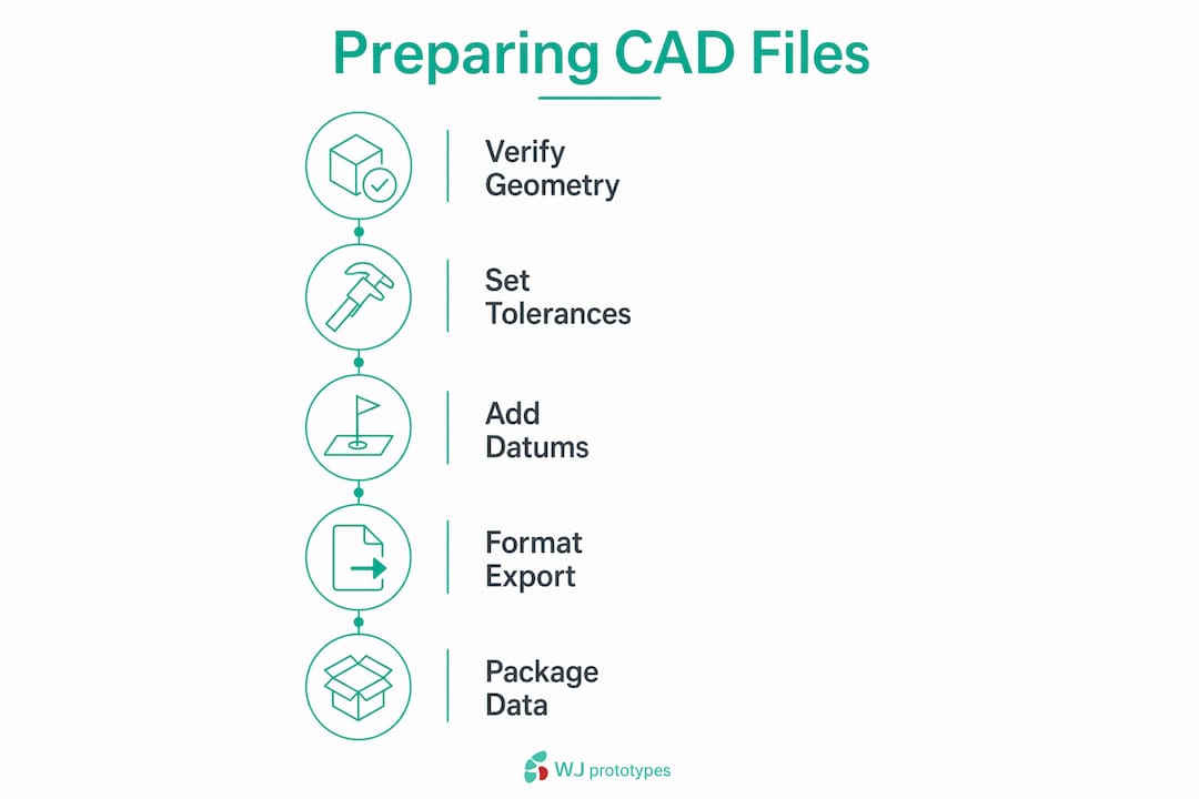
Critical dimensions typically require tolerance bands of ±0.01 mm to ±0.02 mm. Non-critical dimensions use general tolerances around ±0.1 mm. Applying tight tolerances everywhere is a common mistake that drives up cost without improving part function. Reserve tight tolerances for mating surfaces, bearing bores, and functional interfaces.
Datums define the coordinate system your manufacturer uses to set up the part. According to ASME Y14.5, the primary datum constrains 3 degrees of freedom, the secondary constrains 2, and the tertiary constrains 1. Misordering datums causes assemblies to fail even when individual part tolerances are met. Always select datums based on functional surfaces, not convenient flat faces.
Annotation checklist for every manufacturing drawing:
| Dimension Type | Recommended Tolerance | Example Application |
|---|---|---|
| Critical fit (bearing bore) | ±0.01 mm | Shaft-to-bearing interface |
| Mating surface | ±0.02 mm | Flange face, locating pin hole |
| General machined | ±0.1 mm | Non-functional walls, pockets |
| Sheet metal bend | ±0.5 mm | Bracket flanges |
Clear datums and origins reduce setup ambiguity and give machinists a predictable reference for every operation. Skipping this step forces the shop to make assumptions, and assumptions produce scrap.
A complete data package is what separates a smooth production run from a delayed one. Material type and finish requirements must be documented explicitly. Specifying “Aluminum 6061-T6, clear anodize per MIL-A-8625 Type II” leaves no room for interpretation. Specifying “aluminum, anodized” leaves the shop guessing on alloy, temper, and finish class.
Your data package should include the 3D STEP file, the 2D drawing as a PDF, and a separate notes document covering quantity, delivery requirements, and any special inspection criteria. If the part is one component in an assembly, include the assembly drawing so the manufacturer understands how it fits and what surfaces are critical.
Communication best practices for CAD file submission:
Pro Tip: Send a preliminary file for review before finalizing your drawing. Most manufacturers, including Wjprototypes, will flag issues at the quote stage. Catching a datum error or a thin wall before production starts costs nothing. Catching it after costs everything.
For CNC machining precision, the drawing and model must agree completely. Any discrepancy between the 3D geometry and the 2D drawing forces the machinist to stop and ask for clarification, which delays your order.
Missing tolerances, incorrect file formats, and thin walls are the three errors that cause the most manufacturing delays and scrapped parts. Each one is avoidable with a pre-submission checklist.
Common mistakes and how to fix them:
Errors in CAD file preparation lead directly to increased costs, production delays, and scrap parts. A 15-minute pre-submission review eliminates the majority of these issues.
Proper CAD file preparation is the single most effective way to reduce manufacturing errors, cut lead times, and avoid costly rework before production begins.
| Point | Details |
|---|---|
| Choose STEP AP242 | Use AP242 over AP203 to transfer GD&T annotations and avoid missing tolerance data. |
| Verify model geometry | Check for closed solids, thin walls, and undercuts before submitting any file for production. |
| Specify tolerances explicitly | Apply tight tolerances only to critical features; use ±0.1 mm as the general default. |
| Define datums correctly | Follow ASME Y14.5 datum ordering to constrain degrees of freedom and prevent assembly failures. |
| Send a complete data package | Include the STEP file, PDF drawing, material spec, finish, and quantity in every submission. |
The most expensive mistake I see engineers make is treating the 3D model as the complete deliverable. A clean STEP file is necessary, but it is not sufficient. The drawing is where manufacturing intent lives. I have reviewed files where the model was geometrically perfect and the drawing had no tolerances, no datums, and no material call-out. The shop had to guess on everything. The parts came back wrong, and the engineer blamed the manufacturer.
The second pattern I see constantly is over-tolerancing. Engineers apply ±0.01 mm to every dimension because it feels safer. It is not safer. It is more expensive, slower to inspect, and often impossible to hold on standard equipment. Tight tolerances should be reserved for the 10–20% of dimensions that actually drive function. The rest should use general tolerances.
The shift to AP242 STEP exports is one of the most underrated improvements a design team can make. Most teams are still exporting AP203 out of habit. Switching to AP242 means your GD&T travels with the model, your manufacturer’s CAM software can read it directly, and the risk of annotation loss during file transfer drops significantly.
My practical advice: build a pre-submission checklist and make it mandatory for every file that leaves your team. It takes 15 minutes. It saves days. And if you are working with a manufacturer like Wjprototypes that offers DFM review at the quote stage, use it every time. That feedback loop is free engineering consulting.
— Yu
Once your CAD files are verified, annotated, and packaged correctly, the next step is finding a manufacturing partner who can execute on them. Wjprototypes offers CNC machining services backed by ISO certification and experienced engineers who review every file before production starts. Whether you need aluminum, stainless steel, or engineering plastics, the CNC machining materials page covers the full range of options suited for prototypes and custom production parts. For a fast quote on your next project, the CNC machining service page lets you upload your files and get pricing without delay.
STEP AP242 is the recommended format for CNC machining because it transfers geometry and GD&T annotations together. Always pair the STEP file with a 2D PDF drawing for complete manufacturing information.
Apply a general tolerance block (typically ±0.1 mm) in the title block and add explicit tolerances to all critical dimensions. Reserve tight tolerances like ±0.01 mm for mating surfaces and functional interfaces only.
A datum is a reference surface or point used to define the coordinate system for machining and inspection. ASME Y14.5 requires a primary, secondary, and tertiary datum to fully constrain a part’s degrees of freedom.
The 3D model defines geometry for CAM programming, while the 2D drawing carries tolerances, surface finish, material specs, and GD&T callouts. Most shops cannot legally manufacture to a 3D model alone without a drawing to confirm design intent.
Corrupted exports, missing surfaces, and non-manifold geometry are the most common causes. Always open your exported STEP file in a neutral viewer like FreeCAD or eDrawings before sending it to your manufacturer.
SERVICES
RESOURCES