


- Room 1807, Unit 9, Building 2, Shangxing Commercial Street, Shangde Road, Shangxing Community, Xinqiao Subdistrict, Bao'an District, Shenzhen City, China
CONTACT US

WhatsApp

Aerospace & UAV
WJ Prototypes is your 3D manufacturing partner from prototype to large scale production.
Consumer Electronics
New Product Introduction Solutions for Consumer Electronics.

Robotics & Automation
Need some assistance bringing your robotic device or parts from the sketch-board to reality?
Medical Devices
The medical industry needs high quality, dependable and safe parts and products.
Automotive
New Product Introduction Solutions for Automotive
Industrial Machinery
The main purpose of industrial prototyping is to take the product from drawings into the real world.


TL;DR:
Design for manufacturability emphasizes designing products aligned with manufacturing capabilities from the start, reducing costly later modifications. It advocates simplifying geometry, minimizing part count, standardizing tolerances, and planning for fixturing early to cut costs and improve quality. Early collaboration with manufacturers and robust documentation are critical to prevent design errors and ensure efficient production.
Design for manufacturability (DFM) is the engineering discipline of structuring product geometry, tolerances, and material choices to align with real manufacturing process capabilities from the earliest design stage. Most product lifecycle costs are committed during the design phase, which means decisions made at a CAD workstation determine 70 to 80 percent of final production cost before a single part is machined. Design changes made after the concept phase can cost 10 to 100 times more than changes made during initial design. That cost multiplier is the clearest argument for treating DFM not as a final review checkbox, but as a core design constraint from day one. This guide walks through the principles, workflow, and common pitfalls that separate manufacturable designs from expensive redesigns.
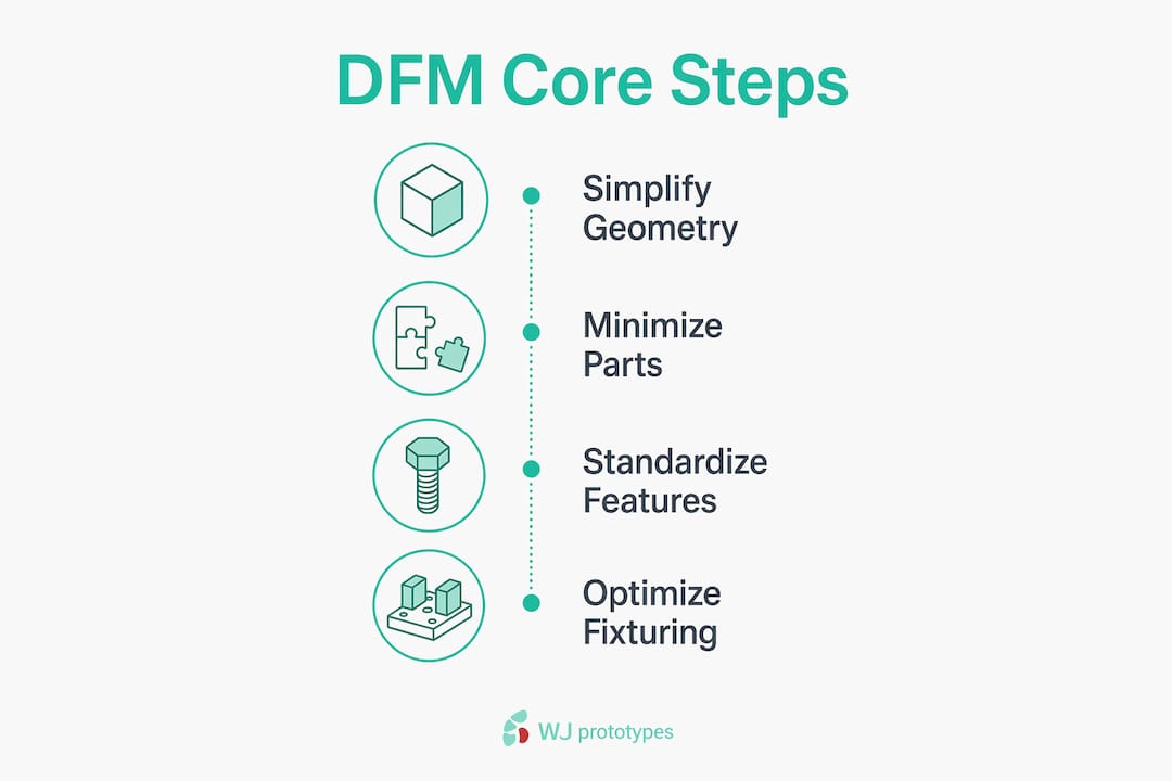
True DFM is a proactive engineering discipline that aligns geometry, tolerances, and materials with real manufacturing realities. It is not a pricing negotiation checklist applied at the end of a project. The following principles form the foundation of every cost-effective design.
Complex internal features, sharp corners, and deep narrow pockets all drive up machining time and tooling cost. Increasing internal radii from 1 mm to 3 mm, for example, reduces cycle time by double digits because the cutting tool can move faster without deflecting. The practical rule: design every internal corner with a radius at least one-third the depth of the pocket.
Secondary operations like manual deburring or EDM steps can increase part cost by 20 to 50 percent compared to simpler designs. Every feature that requires a secondary operation is a cost multiplier you can often eliminate with a geometry revision.
Reducing part count improves assembly time, reliability, and reduces hidden costs because every additional part adds assembly steps, tolerance stacks, and a new failure mode. Ask three questions for each component: Can it be combined with an adjacent part? Can it be eliminated entirely? Can a standard off-the-shelf component replace a custom one?
Simplifying assembly by reducing part count often yields higher savings than optimizing individual parts alone. A single molded bracket replacing three machined pieces eliminates two fasteners, two assembly operations, and two tolerance stack-ups simultaneously.
Specify the loosest tolerance that still satisfies the functional requirement. Over-specifying tolerances elevates machining time, scrap rates, and inspection effort without delivering functional benefit. A ±0.05 mm tolerance on a non-mating surface that could accept ±0.25 mm adds cost with zero engineering justification. You can learn more about tolerance selection in prototyping to calibrate your specs against real process capability.
Standardizing hole sizes, thread forms, and surface finishes across a design lets the shop use common tooling throughout. Every non-standard feature is a tool change, a setup, or a special-order insert.
Robust datums and clamping areas facilitate quicker setups and improve part consistency. Poor fixturing design increases cycle time and dimensional variability because the machine operator must improvise a hold-down solution. Design flat, parallel datum surfaces into the part wherever the form allows. Poor fixture design requiring custom tooling or manual part handling significantly slows cycle time and harms dimensional control.
Comparison: DFM-optimized vs. non-optimized design choices
| Design decision | Non-optimized | DFM-optimized |
|---|---|---|
| Internal corner radius | 0.5 mm (sharp) | 3 mm (tool-friendly) |
| Tolerance on non-mating face | ±0.05 mm | ±0.25 mm |
| Part count for bracket assembly | 4 parts, 6 fasteners | 1 molded part |
| Surface finish spec | Ra 0.4 µm everywhere | Ra 0.4 µm on sealing faces only |
| Datum surfaces | Implied from CAD origin | Explicit flat pads machined in |
Pro Tip: When selecting materials early in the design process, check material availability for CNC against your target process. A material that requires special cutting parameters can negate every geometry optimization you made.
The DFM validation lifecycle follows four structured stages: Concept, Engineering Validation, Design Validation, and Production Validation. Each stage has a specific gate that prevents expensive problems from propagating forward.
Pro Tip: Pair DFM with Design for Assembly (DFA) analysis. DFA focuses specifically on reducing assembly time and error risk, and the two disciplines together consistently deliver greater cost reduction than either one applied alone. Explore how prototyping reduces manufacturing costs at each validation stage.
Most manufacturability problems trace back to a small set of recurring errors. Recognizing them early is faster than correcting them late.
"A design that cannot be manufactured consistently and economically is not a finished design. It is a cost problem waiting to be discovered on the shop floor."
Modern CAD platforms and simulation tools have made DFM analysis accessible at every stage of the design process. The gap between theoretical design and manufacturable geometry is now measurable in software before any physical part is made.
DFM tool capabilities by category
| Tool category | Examples | Primary DFM function |
|---|---|---|
| CAD with DFM modules | SolidWorks, PTC Creo, Autodesk Fusion | Draft analysis, wall thickness, undercut detection |
| Mold flow simulation | Moldex3D, Autodesk Moldflow | Fill analysis, weld line prediction, sink mark location |
| Cost modeling | aPriori, Costimator | Feature-level cost estimation, process comparison |
| Cloud collaboration | Onshape, GrabCAD | Shared model access, revision control with suppliers |
| Rapid prototyping | SLA, SLS, FDM 3D printing | Physical validation of geometry and assembly fit |
Early prototyping with SLA or SLS 3D printing lets you validate assembly fit, fixturing access, and ergonomics before committing to hard tooling. For injection-molded parts, soft aluminum tooling can produce functional samples at a fraction of the cost of production steel tooling, giving you one more opportunity to catch DFM issues before they become permanent. WJ Prototypes offers both rapid prototyping and low-volume manufacturing to support this validation stage.
Involving a contract manufacturer during the digital design phase, rather than at the drawing release stage, compresses the feedback loop dramatically. A manufacturer reviewing a STEP file can identify fixturing problems, flag non-standard tooling requirements, and suggest geometry changes in hours. The same feedback delivered after tooling is cut costs orders of magnitude more to act on.
Pro Tip: Use cloud-based collaboration platforms like Onshape or GrabCAD to share live CAD models with your manufacturing partner. Static PDF drawings create version control problems. Live model access eliminates them.
Effective DFM requires locking in geometry, tolerances, and material choices against real manufacturing constraints before the design is released, because cost is committed at the design stage and corrections multiply in expense at every subsequent phase.
| Point | Details |
|---|---|
| Cost is committed early | Design changes post-concept cost 10 to 100 times more, making early DFM the highest-leverage investment. |
| Simplify geometry and part count | Increasing internal radii and consolidating parts cuts cycle time, assembly risk, and total cost simultaneously. |
| Standardize tolerances | Specify the loosest tolerance that satisfies the function; over-tight specs increase scrap and inspection cost with no benefit. |
| Use structured ECO processes | Formal change control prevents version drift and confirms all teams build from the correct, current design. |
| Collaborate with manufacturers early | Bringing manufacturing partners in at the concept stage surfaces fixturing, tooling, and material constraints before they become expensive problems. |
The standard DFM conversation focuses on geometry and tolerances, and that focus is correct. But in my experience working across CNC machining, injection molding, and sheet metal fabrication projects, the most expensive problems rarely come from a radius that is too tight or a tolerance that is too strict. They come from a drawing that does not match the CAD model, a revision that was never formally released, or a material specification that was updated in an email thread but never captured in the drawing package.
Version drift is the silent cost multiplier that DFM guides rarely address directly. A team can execute every geometry optimization correctly and still produce a batch of scrap parts because the shop ran the previous revision. Implementing a formal ECO process from the first prototype is not bureaucratic overhead. It is the mechanism that makes every other DFM improvement actually reach the production floor.
The second insight I would offer is about part count reduction. Engineers often frame consolidation as a cost exercise, and it is. But the reliability argument is equally strong. Every interface between two parts is a tolerance stack-up, a fastener that can loosen, and a surface that can corrode or wear. Fewer parts means fewer failure modes, a shorter bill of materials, and a simpler supply chain. When I see a design with 40 components, I ask what the minimum viable part count is. The answer is almost always lower than the designer expected, and the cost and reliability improvements follow automatically.
The third habit that separates strong DFM practitioners from average ones is designing with the fixture in mind from the first sketch. Most designers think about the part. The best designers think about how the part will be held, located, and inspected. That mental shift changes geometry decisions at the concept stage, which is exactly when they are cheapest to make.
— Nas
WJ Prototypes provides CNC machining, injection molding, die casting, and rapid prototyping services from China, with engineering support designed to catch manufacturability issues before they reach production. The team reviews geometry, tolerances, and fixturing requirements as part of the quoting process, giving you direct feedback on cost drivers in your design. Explore the full range of CNC machining materials optimized for prototypes and custom parts, or get a quote directly through CNC machining services to validate your design against real process capabilities. Early collaboration with WJ Prototypes at the concept or engineering validation stage compresses your feedback loop and reduces the risk of costly late-stage redesigns.
Explore competitive Rapid Prototyping Services with expert support from WJ Prototypes.
Whether you're comparing suppliers or looking to optimize costs, our team can help you evaluate the best option for your project.
👉 Request A Quote now or email us at info@wjprototypes.com to get started.
Design for manufacturability (DFM) is the engineering practice of optimizing product geometry, tolerances, and material choices to align with manufacturing process capabilities, reducing production cost and complexity from the earliest design stage.
DFM analysis should begin at the concept stage, before detailed CAD work starts. Design changes made during the concept phase cost 10 to 100 times less than changes made after tooling or production has begun.
The highest-impact steps are reducing part count, relaxing non-functional tolerances, simplifying internal geometry, and designing explicit datum and clamping surfaces. These four changes address the majority of avoidable manufacturing cost in most designs.
DFM focuses on making individual parts easier and cheaper to manufacture. Design for assembly (DFA) focuses on reducing the time, steps, and error risk in assembling those parts. The two disciplines are complementary and most effective when applied together.
SolidWorks, PTC Creo, and Autodesk Fusion all include DFM analysis modules that check draft angles, wall thickness, and undercuts. For injection-molded parts, Moldex3D and Autodesk Moldflow add mold flow simulation to predict fill and defect locations before tooling is cut.
Sheet Metal Design Tips for Prototyping Efficiency
Industrial Prototyping Guide For Engineers In 2026
What Is Digital Manufacturing? A Guide For Engineering Teams
How to Prototype Parts | Step-by-Step Guide for Professionals
Explore competitive Rapid Prototyping Services with expert support from WJ Prototypes.
Whether you're comparing suppliers or looking to optimize costs, our team can help you evaluate the best option for your project.
👉 Request A Quote now or email us at info@wjprototypes.com to get started.
SERVICES
RESOURCES


