


- Room 1807, Unit 9, Building 2, Shangxing Commercial Street, Shangde Road, Shangxing Community, Xinqiao Subdistrict, Bao'an District, Shenzhen City, China
CONTACT US

WhatsApp

Contact Us
Our team is on stand by, waiting toassist you.
Videos
A large collection of educational videos and tutorials.
About Us
Learn about our company, leadership, and mission totransform manufacturing.
Privacy Policy
Applies to all personal information collected through and/or processed in connection.

Aerospace & UAV
WJ Prototypes is your 3D manufacturing partner from prototype to large scale production.
Consumer Electronics
New Product Introduction Solutions for Consumer Electronics.

Robotics & Automation
Need some assistance bringing your robotic device or parts from the sketch-board to reality?
Medical Devices
The medical industry needs high quality, dependable and safe parts and products.
Automotive
New Product Introduction Solutions for Automotive
Industrial Machinery
The main purpose of industrial prototyping is to take the product from drawings into the real world.

TL;DR:
A micron-level deviation in a spinal implant can determine the success or failure of the surgery, highlighting the critical importance of precise tolerance management.
In aerospace and medical sectors, prototypes require extremely tight tolerances to ensure safety and performance, while looser tolerances are acceptable in automotive and consumer electronics to reduce costs.
Properly specifying, analyzing, and verifying tolerances using standards like GD&T and stack-up analysis is essential to optimize prototype quality, cost, and development speed.
A single micron of deviation in a spinal implant can mean the difference between a successful surgery and a catastrophic failure. In aerospace assemblies, a misaligned jet turbine blade tolerance of just ±0.02mm above spec can trigger vibration failures at altitude. These aren't edge cases; they're real consequences that product development teams face when tolerance strategy is treated as an afterthought. Tolerance in prototyping refers to the permissible limit of variation in a physical dimension of a prototype part, ensuring form, fit, and function in assemblies despite manufacturing variations. This guide covers definitions, sector benchmarks, analysis methods, and practical best practices to sharpen your prototyping process.
| Point | Details |
|---|---|
| Tolerance is crucial | Allows parts to fit and function reliably even as manufacturing varies. |
| GD&T sets the rules | Use standard frameworks to control not just size but position, form, and orientation. |
| Benchmarks vary by industry | Medical and aerospace often need much tighter tolerances than automotive. |
| Validate before scaling | Always check tolerances in prototype builds to prevent costly errors in production. |
| Avoid overengineering | Tighter isn't always better—set tolerances based on function, not gut feeling. |
To ground this in the work of engineers, let's unpack exactly what "tolerance" means in a prototyping context.
Tolerance is the allowable range of dimensional variation a manufactured part can exhibit and still perform its intended role. When a drawing callout reads ±0.05mm on a bore diameter, it means the final part can measure anywhere from 0.05mm under to 0.05mm over the nominal value and pass quality inspection. That sounds simple. In practice, it drives virtually every decision in your manufacturing workflow.
"Tolerance in prototyping refers to the permissible limit of variation in a physical dimension of a prototype part, ensuring form, fit, and function in assemblies despite manufacturing variations."
Tolerance directly impacts three critical outcomes:
The stakes scale with complexity. An aerospace propulsion assembly may include hundreds of parts, each with its own tolerance band. Even small individual errors compound across the stack and can prevent final assembly or cause downstream failures. A hip implant toleranced too loosely may rock in the acetabular cup, accelerating wear and requiring revision surgery. A car door panel toleranced imprecisely creates panel gaps that ruin perceived quality scores.
What makes prototyping distinct is that designers often allow slightly wider tolerances than production parts, especially in early concept or functional test phases. This flexibility supports rapid iteration and reduces per-part cost. However, teams must understand which features are safety-critical or assembly-defining, because those features need to mirror production tolerances even at the prototype stage. Material selection in prototyping compounds this further, since some materials like SLA resins and powder-sintered nylons inherently hold tighter tolerances than others and must be factored into design decisions early.
The mistake most teams make is applying blanket tolerance rules across an entire prototype rather than tiering tolerances by feature criticality. That single oversight drives unnecessary cost and, paradoxically, increases rework when critical interfaces fail.
Once the basics are clear, the next step is understanding how to specify and manage tolerances using industry standards and proven strategies.
The most widely used framework for communicating tolerances is Geometric Dimensioning and Tolerancing (GD&T). GD&T per ASME Y14.5 or ISO standards controls form, orientation, and position beyond simple linear dimensions. It replaces ambiguous coordinate-based callouts with a precise symbolic language that defines exactly what's being controlled and how it's measured. A position callout in GD&T, for example, defines a cylindrical tolerance zone around the true position of a hole, which is far more functional than a simple ±X, ±Y coordinate tolerance.
Here's a quick comparison of the two dominant standards:
| Feature | ASME Y14.5 (US) | ISO GPS |
|---|---|---|
| Primary market | North America, aerospace | Europe, automotive, medical |
| Datum reference | Feature-based, explicit | Theoretical exact geometry |
| Unambiguous modifiers | Yes (MMC, LMC, RFS) | Partial coverage |
| Default tolerances | Referencing title block | ISO 2768 general tolerances |
| Common in prototyping | CNC, injection molding | CNC, sheet metal, DMLS |
Tolerance stack-up analysis is the next essential concept. You cannot evaluate individual feature tolerances in isolation when building a complex assembly. Stack-up analysis calculates how individual variations accumulate and predicts worst-case or statistical assembly outcomes. Digital tools like CETOL 6σ and 3DCS allow engineers to simulate dimensional variation before cutting a single part, catching interference risks and clearance failures in the design phase. This is far cheaper than discovering the problem during physical assembly.
A practical workflow for integrating tolerance analysis into your prototyping cycle:
Pro Tip: The most costly tolerance error is not a part that fails inspection. It's a part that passes inspection but fails in assembly because the stack-up was never analyzed. Before committing to a build, run at least a worst-case stack-up on your three most critical interfaces. It takes hours and can save weeks of rework. Teams choosing prototyping services should verify that suppliers can deliver GD&T-compliant inspection reports, not just dimensional printouts.
Understanding the cost implications is also essential. Tighter tolerances require more machine time, more frequent tool changes, and more rigorous inspection, all of which raise per-part cost. Cost-effective prototyping depends on matching tolerance specifications to the actual functional need. When a surface tolerance is unnecessarily tight, you pay a premium that doesn't improve prototype performance.
With methods and standards in place, it's vital to anchor expectations with real figures from your industry.
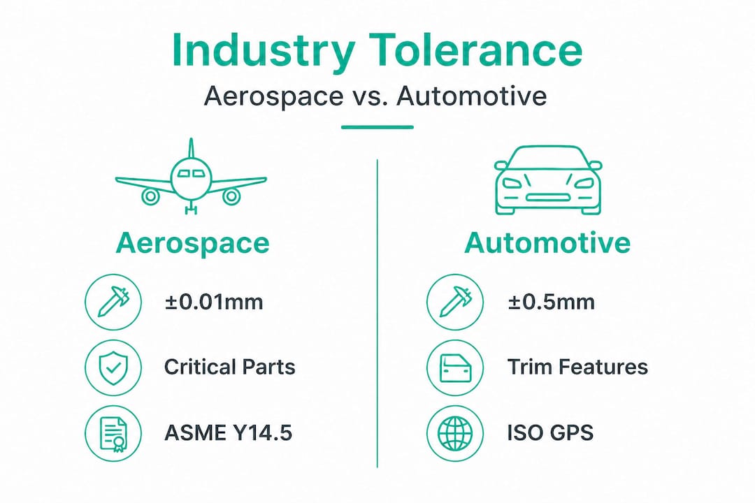
Aerospace and medical sectors demand ±0.01mm or tighter on critical features such as implants and turbine blades, while automotive typically targets ±0.05mm in production and allows looser tolerances for prototypes. ISO 2768-mK serves as a common default general tolerance, delivering roughly ±0.1mm at a 50mm nominal dimension.
Here's how those numbers map to real parts across three sectors:
| Sector | Critical feature tolerance | Typical prototype tolerance | Common standard | Key driver |
|---|---|---|---|---|
| Aerospace | ±0.005 to ±0.01mm | ±0.01 to ±0.025mm | AS9100, ASME Y14.5 | Safety, fatigue life |
| Medical | ±0.005 to ±0.01mm | ±0.01 to ±0.02mm | ISO 13485, FDA guidance | Biocompatibility, fit |
| Automotive | ±0.05mm (production) | ±0.1 to ±0.2mm | IATF 16949, ISO 2768 | Volume consistency |
| Consumer electronics | ±0.1mm | ±0.2mm | ISO 2768-mK | Cosmetic, assembly |
These numbers tell an important story. Aerospace and medical prototyping operates at tolerances that are often 5 to 10 times tighter than automotive production parts. That is not because engineers in those sectors are perfectionists. It is because the consequences of failure are fundamentally different.
Consider a prosthetic knee joint prototype. The tibial insert must fit precisely into the tray component within ±0.01mm on the bearing surface. Even a 0.03mm deviation can alter the load distribution across the polyethylene, increasing wear rates by an order of magnitude. In a turbine blade for jet propulsion, a profile tolerance deviation beyond ±0.01mm changes the aerodynamic behavior of the blade and can induce resonant vibration at operating RPMs.
Automotive tells a different story. Interior panels and trim components prototype at ±0.5mm or even looser, because the functional requirement is visual alignment and tactile feel, not structural integrity. Using aerospace-level tolerances on a dashboard prototype is not just unnecessary; it actively wastes budget and delays tooling decisions.
One statistic worth internalizing: in zero-failure tolerance environments like implantable medical devices, a single out-of-tolerance part reaching a patient can trigger a full device recall affecting tens of thousands of units. The financial and reputational cost makes upfront tolerance investment trivially small by comparison.
Understanding the aerospace prototyping process and medical device prototyping requirements from the outset shapes every downstream decision, from process selection to inspection protocols. Engineers working in these sectors often underestimate how quickly suppliers unfamiliar with sector-specific demands can introduce tolerance errors that require costly re-runs.
Achieving the right tolerance is only half the battle. Rigorous validation and smart optimization are key to delivering reliable prototypes and controlling cost.
In aerospace and medical sectors, validation via prototypes and Monte Carlo analysis is the standard approach given zero-failure requirements, while automotive favors RSS (root sum square) methods for higher volume scenarios. The core principle across all three is this: always match tolerances to the process capabilities of your chosen manufacturing method to avoid rework.
Here's what a structured validation cycle looks like in practice:
"Matching tolerances to prototype process capabilities is not optional in high-stakes sectors. It is the primary mechanism for controlling rework cycles and protecting launch timelines."
Monte Carlo simulation is particularly powerful because it runs thousands of virtual assembly trials with randomized part variations, revealing not just worst-case outcomes but the probability distribution of assembly success. For a medical device with 12 mating components, this kind of statistical insight is non-negotiable.
Pro Tip: During early-stage functional prototypes, deliberately loosen tolerances on non-critical geometry by one full ISO 2768 grade. This keeps iteration fast and affordable. Lock in tight tolerances only when you're validating final production geometry. Teams that conflate early-stage concept builds with final design validation end up spending 40 to 60 percent more per prototype cycle than necessary. Investing in precision engineering in prototyping at the right stage is how you control total program cost, not by applying maximum precision everywhere from day one.
Bringing it all together, here's what experience tells us about the reality behind the numbers.
There is a deep-seated belief in engineering culture that precision is always virtuous. Tighter tolerances mean better parts, more professional drawings, and lower risk. In practice, that belief costs companies significant time and money every year.
When a team specifies ±0.005mm tolerances on features that only need ±0.05mm, the impact is immediate and compounding. Machining time increases. Tool wear accelerates. Inspection takes longer. Scrap rates rise. And when the supplier cannot hit the tolerance with the designated process, rework cycles begin. None of that adds functional value to the prototype.
The silent risk of overengineering is the missed market window. In competitive sectors like automotive consumer electronics integration or wearable medical devices, speed to functional prototype directly affects competitive positioning. A team that spends six weeks chasing unnecessary precision on a concept validation prototype loses ground to a team that built three iterations in the same timeframe by applying smart tolerance tiering.
The real lesson from high-stakes sectors is that precision matters in context, not in absolute terms. The aerospace engineers who designed the most reliable jet engines did not specify maximum tightness on every feature. They identified exactly which dimensions were load-bearing, fatigue-critical, or aerodynamically active, and applied precision surgically to those features. Everything else was toleranced pragmatically.
There are also real cases where loosening a tolerance solved a manufacturing problem. One common example: a medical enclosure with a ±0.02mm flatness spec on a non-sealing surface was causing 30 percent scrap rates at the prototype stage. Relaxing it to ±0.1mm eliminated the scrap without any measurable change in device function or patient-facing performance. Understanding the cost-saving benefits of prototyping means recognizing that smart tolerance decisions are a cost lever, not a quality compromise.
The engineer who asks "what tolerance does this feature actually need?" adds more value than the one who defaults to "as tight as possible."
If you're ready to take prototyping reliability to the next level, specialized partners can make all the difference.
Managing tolerances across aerospace, medical, and automotive prototypes requires more than good drawings. It requires suppliers who understand GD&T, perform stack-up analysis, and deliver calibrated CMM inspection reports as standard. At WJ Prototypes, our ISO-certified manufacturing team works with product development engineers globally to achieve the exact tolerances your sector demands, from CNC machining services capable of holding ±0.01mm on critical features to a full range of CNC machining materials selected for process compatibility and dimensional stability. We combine fast turnaround with rigorous quality control so your prototype builds stay on spec and on schedule, without inflating your budget with unnecessary overengineering.
Explore competitive Rapid Prototyping Services with expert support from WJ Prototypes.
Whether you're comparing suppliers or looking to optimize costs, our team can help you evaluate the best option for your project.
👉 Request A Quote now or email us at info@wjprototypes.com to get started.
It means a part's dimension can vary by up to 0.01mm above or below the target value and still pass quality inspection, which is the standard for critical features in aerospace and medical applications.
Prototypes focus on functional testing and speed, so not all features need final production tightness. Automotive production targets ±0.05mm but allows wider bands in prototype phases to reduce cost and lead time.
Geometric Dimensioning and Tolerancing (GD&T) clarifies and controls feature relationships using a standardized symbolic language. GD&T per ASME Y14.5 or ISO standards reduces drawing ambiguity and prevents assembly failures by specifying exactly what is controlled and how.
Balance functionality, risk, and process capability by referencing industry benchmarks and required performance. Prioritizing GD&T and stack-up analysis early in the prototyping cycle helps teams optimize tolerances for precision sectors without over-specifying on non-critical features.
Parts may fail inspection, require costly rework, or create assembly difficulties that delay projects. Matching tolerances to process capabilities is the most effective way to prevent this outcome from the start.
How to Choose Prototyping Method for Precision Projects
How to Choose Prototyping Services for Precision Results
Precision Engineering in Prototyping: Driving Breakthroughs
Role Of Prototyping In Innovation For Precision Sectors
How to improve production efficiency with data in 2026
Explore competitive Rapid Prototyping Services with expert support from WJ Prototypes.
Whether you're comparing suppliers or looking to optimize costs, our team can help you evaluate the best option for your project.
👉 Request A Quote now or email us at info@wjprototypes.com to get started.
SERVICES
RESOURCES


