


- Room 1807, Unit 9, Building 2, Shangxing Commercial Street, Shangde Road, Shangxing Community, Xinqiao Subdistrict, Bao'an District, Shenzhen City, China
CONTACT US

WhatsApp

Aerospace & UAV
WJ Prototypes is your 3D manufacturing partner from prototype to large scale production.
Consumer Electronics
New Product Introduction Solutions for Consumer Electronics.

Robotics & Automation
Need some assistance bringing your robotic device or parts from the sketch-board to reality?
Medical Devices
The medical industry needs high quality, dependable and safe parts and products.
Automotive
New Product Introduction Solutions for Automotive
Industrial Machinery
The main purpose of industrial prototyping is to take the product from drawings into the real world.


TL;DR:
Modern additive manufacturing enables complex geometries that traditional methods cannot efficiently produce.
Hybrid workflows combining additive and subtractive processes optimize performance, cost, and time.
Proper design and process planning are crucial to avoiding defects and maximizing complex geometry benefits.
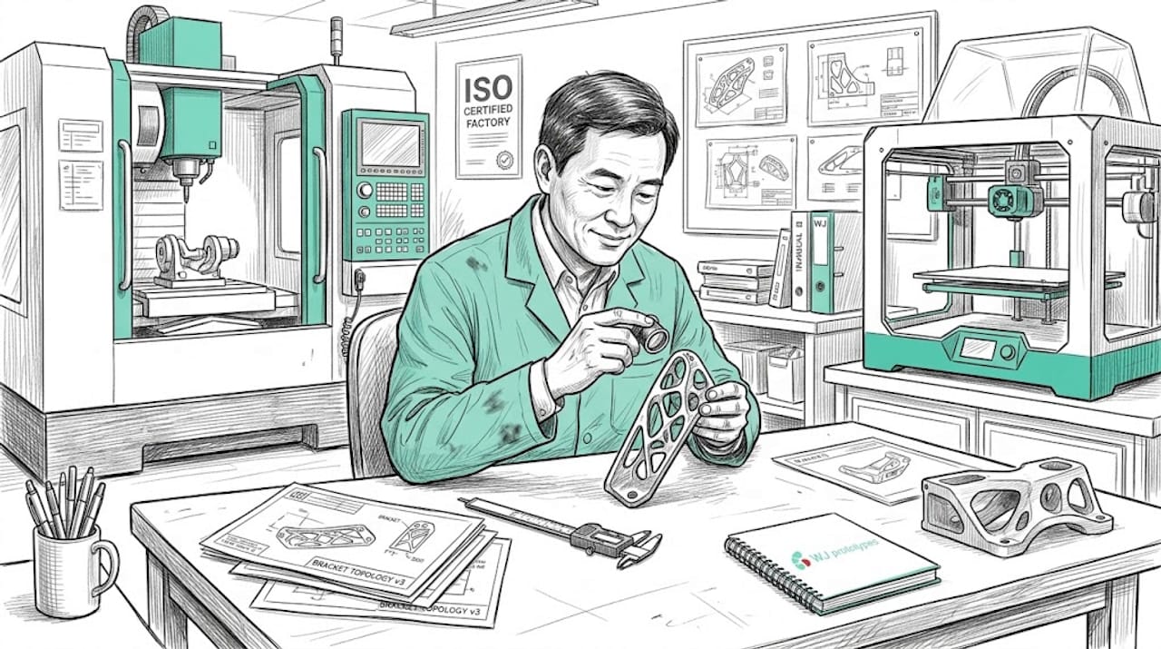
Complex geometry used to mean one thing: expensive, slow, and risky to prototype. That assumption is costing engineering teams real money. Modern additive manufacturing, hybrid workflows, and topology optimization have fundamentally changed what's achievable, and at what cost. Whether you're developing aerospace brackets, automotive fluid manifolds, or medical implants, understanding which tools match your geometry is no longer optional. This guide walks through what defines complexity in a prototyping context, which methods handle it best, where teams go wrong, and how to get the most from your process choices.
| Point | Details |
|---|---|
| Geometry drives innovation | Sophisticated shapes enable breakthrough performance, especially in aerospace and medical prototyping. |
| Choose the right method | AM, CNC, and hybrid methods each excel in different areas—select based on geometry, precision, and volume. |
| Avoid design pitfalls | Work with DfAM and cross-functional teams early to prevent known process issues and material mismatches. |
| Validate for quality | For regulated sectors, rigorously test and document prototypes to ensure compliance and performance. |
Not every difficult part qualifies as geometrically complex. In an engineering context, complexity refers to features that conventional subtractive or formative processes can't easily produce without significant cost or compromise.
The most common markers of complex geometry include:
These features aren't just aesthetic. They exist because performance demands it. In aerospace, a bracket that saves 200 grams across 400 units has a compounding effect on fuel economy. In medical devices, internal channel geometry controls drug delivery rates or fluid dynamics in ways a solid block never could.
Traditional CNC machining and injection molding hit real walls here. Multi-axis CNC can handle overhangs and complex pockets, but internal voids are off-limits. Standard injection molding handles volume well but demands draft angles, uniform walls, and accessible parting lines, features that often contradict performance geometry.
The material selection in prototyping also becomes more constrained when geometry is complex. Some high-performance polymers or metals don't behave predictably in complex-shaped molds or under multi-pass machining.
The performance upside is substantial. Recent benchmarks demonstrate a 58.8% mass reduction (from 920g to 542g), 14x less raw material consumed (from 14kg to 673g), and 72% weight savings versus equivalent parts in solid metals like aluminum and steel. On the compliance side, iglidur i3 polymer components reached 30x abrasion resistance versus standard bearings, and aerospace-grade parts achieved CPK values at or above 1.67, meeting strict regulatory thresholds.
"The most innovative geometry isn't complex for complexity's sake. It's the geometry that exists precisely because it couldn't be manufactured any other way."
Once you understand what constitutes complexity, the next question is: how do you prototype such parts most efficiently?
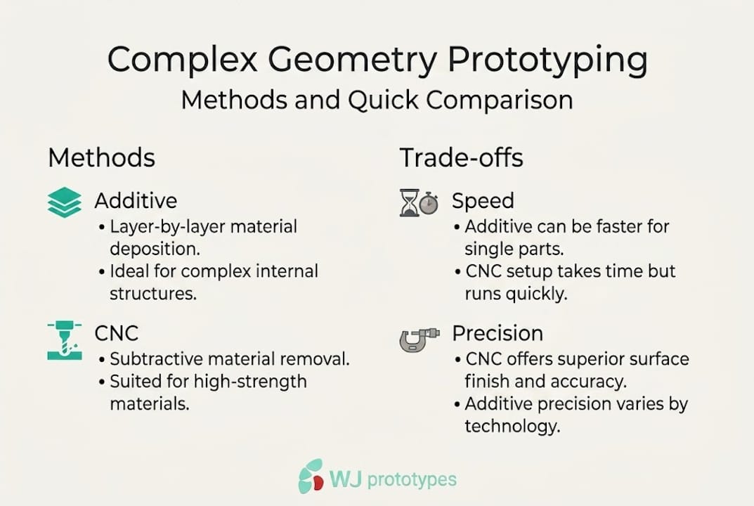
Four process families dominate: additive manufacturing (AM), CNC machining, injection molding and casting, and hybrid workflows that combine multiple methods. Each has a defined role.
| Method | geometric freedom | speed | cost (low vol.) | tolerances | best volume range |
|---|---|---|---|---|---|
| AM (SLS/MJF/Medium | High | Fast | Low | Medium | 1-250 units |
| CNC machining | Medium | Medium | Medium | Very high | 1-500 units |
| injection molding | Low | High (after tooling) | High upfront | High | 1,000+ units |
| hybrid (AM + CNC) | Very high | Medium | Medium | High | 5-500 units |
For most complex geometry prototyping, additive manufacturing examples show that AM handles internal features, lattice infill, and organic contours that no other single process can match. It's cost-effective for low-volume runs of 1 to 50 parts, with the break-even point versus CNC typically landing between 50 and 250 units depending on part complexity, material, and required tolerances.
Choosing the right method follows a logical sequence:
Pro tip: When designing for AM, apply Design for precision engineering in prototyping principles from the start. DfAM means eliminating supports where possible, consolidating multi-part assemblies, and exploiting the freedom that no other process provides. Don't just replicate a CNC part in an AM machine.
With the core methods compared, let's dig deeper into how to choose, and combine, processes based on your precise project demands.
AM is not a single process. Layer thickness is a critical variable. A finer layer (for example, 30 microns in metal powder bed fusion) improves surface finish and dimensional accuracy but increases build time. A thicker layer (100 microns) cuts time but raises porosity risk in tall builds where melt pool stability varies. Build height also affects residual stress accumulation, which matters enormously in regulated industries. For aerospace (under AS9102 requirements) or medical device programs (under FDA or CE pathways), these variables must be validated, not assumed.
Topology optimization is where AM truly earns its value in performance applications. By using software to redistribute material only where loads require it, engineers produce parts that are lighter and stronger, but also shapes that are only manufacturable via AM. The trade-off is validation complexity.
| Variable | AM | CNC | hybrid |
|---|---|---|---|
| precision (typical) | +/- 0.1 to 0.3mm | +/- 0.01 to 0.05mm | +/- 0.02 to 0.1mm |
| productivity (batch) | High for complex | High for simple | Medium |
| tooling cost | None | Low (fixtures) | Medium |
| regulatory approval path | Complex | Well-established | Complex but structured |
CNC remains the gold standard for tight tolerances and high-strength material removal. A common hybrid strategy is to AM the net shape (capturing all the internal complexity), then CNC machine critical interface surfaces to tight tolerance. This is standard practice in turbine component prototyping and orthopedic device development.
Pro tip: For any AM prototype targeting regulatory approval, validate process parameters first on witness coupons. Good manufacturing quality control practice means documenting layer parameters, material batch numbers, and machine calibration records before any design validation testing begins.
Understanding the full scope of types of additive manufacturing available for your material class is critical here. SLS, MJF, and binder jetting behave very differently from metal powder bed fusion, and each has a different tolerance and compliance profile.
The rapid prototyping benefits are real, but they don't come free of trade-off decisions. Every project needs an honest process assessment before committing.
Once you've chosen your method, getting the full benefit depends on how you design and prepare your part.
Common failure modes in complex prototype development include stair-stepping artifacts from horizontal overhangs, anisotropic mechanical properties in parts loaded perpendicular to the build direction, and feature loss in walls thinner than 0.8mm for most polymer AM systems. These aren't hypothetical. They're the issues that show up in first articles and cause expensive design loops.
Following a structured additive manufacturing workflow from the start prevents most of these issues.
Best practices for complex geometry prototypes:
Pro tip: AM applications in aerospace and automotive show consistently that teams who engage their manufacturing partner during design, not after, reduce redesign cycles by significant margins. Share your DfAM constraints early. It's not a weakness. It's how fast programs stay fast.
Theory and guidelines are critical, but real-world examples bring the topic to life and demonstrate potential payoffs.
The numbers from actual AM complex geometry programs are striking. Published benchmarks from aerospace structural prototyping show 58.8% mass reduction (920g to 542g), 14x less raw material used (14kg to 673g versus conventional stock removal), and 72% weight savings over equivalent solid metal designs. These are not theoretical projections. They are measured outcomes from real flight-hardware prototype programs.
In the medical device field, tribologically optimized polymer components using iglidur i3 achieved 30x abrasion resistance improvements over standard bearing materials, enabling implant and instrument prototypes that outperform conventionally manufactured equivalents in wear testing.
What successful teams did differently:
"The role of prototyping innovation in regulated industries isn't about printing faster. It's about validating smarter."
For teams exploring AM examples for aerospace, these results highlight that the technology is mature enough for serious program milestones, not just concept models.
Here's an uncomfortable truth: most engineering teams still choose their prototyping process based on what they already know, not what the part actually needs. CNC shops choose CNC. AM service providers default to AM. That's a bias problem, not a technical one.
The best programs we see treat process selection as a design decision. They start with performance targets, then work backward to the right combination of tools. That often means AM for the complex internal geometry, CNC for the critical datum surfaces, and digital simulation to validate before physical build.
Manufacturing trends heading into 2026 show hybrid and digital workflow adoption accelerating sharply, particularly in sectors where compliance pressure and time-to-market compete directly. This isn't a coincidence. It's because hybrid workflows are the only way to simultaneously satisfy geometric freedom, dimensional precision, and regulatory documentation requirements.
"Single-process thinking is the biggest hidden cost in complex prototype programs. The switch to hybrid workflows often saves more time than any individual process improvement."
If you're evaluating choosing prototyping services for your next program, the question isn't which technology is best. It's which partner can execute across technologies without you having to manage three separate vendors.
Putting this into practice requires more than knowledge. It requires access to the right machines, materials, and engineering support under one roof. WJ prototypes offers the full process stack: SLA, SLS, MJF, and CNC machining materials covering metals and high-performance polymers for complex geometry programs. For automotive development teams, injection molding for automotive applications is available alongside AM for early-stage prototyping, giving you flexibility at every phase. Whether your need is a single functional prototype or a low-volume production bridge, custom injection molding services and AM capabilities are ready to support it. Get an instant quote and connect with experienced engineers who understand regulated industry requirements.
Explore competitive Rapid Prototyping Services with expert support from WJ Prototypes.
Whether you're comparing suppliers or looking to optimize costs, our team can help you evaluate the best option for your project.
👉 Request A Quote now or email us at info@wjprototypes.com to get started.
Choose AM for internal features, organic shapes, and low-volume complex parts where the break-even versus CNC falls between 50 and 250 units. Use CNC when tight tolerances and high-strength materials are the primary requirement.
Apply DfAM principles from the start, orient critical features along the build axis, and use hybrid post-processing where surface quality or strength is critical. DfAM practices are the most reliable method to avoid these issues.
Real AM programs have documented 58.8% mass reductions and CPK compliance at or above 1.67, meeting strict aerospace standards while cutting raw material use by up to 14x.
For complex parts in regulated industries, hybrid workflows typically reduce total program time and cost because hybrid adoption trends show better cost and timeline performance than forcing a single process to handle all requirements.
Precision Engineering in Prototyping: Driving Breakthroughs
Sheet Metal Fabrication Workflow for Prototyping in China
7 Essential Rapid Prototyping Tips for Engineers | China Sourcing Guide
Prototyping in Aerospace: Complete Process Guide
The Future of Building Design: DSM Modelling Explained - Complete EPC
Explore competitive Rapid Prototyping Services with expert support from WJ Prototypes.
Whether you're comparing suppliers or looking to optimize costs, our team can help you evaluate the best option for your project.
👉 Request A Quote now or email us at info@wjprototypes.com to get started.
SERVICES
RESOURCES


